Table of Contents
Advertisement
Quick Links
Advertisement
Table of Contents

Related Manuals for Ross SRG-2200


Summary of Contents for Ross SRG-2200
- Page 1 SRG-2200 User Guide...
- Page 2 Ross has become well known for the Ross Video Code of Ethics. It guides our interactions and empowers our employees. I hope you enjoy reading it below. If anything at all with your Ross experience does not live up to your expectations be sure to reach out to us at solutions@rossvideo.com.
- Page 3 Ross Video. While every precaution has been taken in the preparation of this document, Ross Video assumes no responsibility for errors or omissions. Neither is any liability assumed for damages resulting from the use of the information contained herein.
- Page 4 If you need more information on the collection, reuse, and recycling systems, please contact your local or regional waste administration. You can also contact Ross Video for more information on the environmental performances of our products. Company Address Ross Video Limited...
-
Page 5: Table Of Contents
Initial Product Inspection ............................17 Operating Environment Requirements ........................17 Rack Mount Installation ............................18 Installing the SRG-2200 into a Rack Unit ......................18 Installing the Rear Support Brackets ........................18 Connecting Power ..............................19 Setting the Initial IP Address ..........................19 Configuring the DIP Switches .......................... - Page 6 Network Settings ..............................30 Option Enable Settings ............................30 Calibration Settings .............................30 Operational Configuration ............................31 DashBoard Menus SRG-2200 Status and Genlock Tabs ........................33 Status Tabs ................................33 Genlock Tab ................................34 PSU Status Tab ..............................36 Slot 1: SDI Video and Embedded Audio Tab ......................36 SDI 1 Video Parameters Tab ..........................36...
- Page 7 Exterior Cleaning ..............................91 Preventive Maintenance ............................91 Servicing ................................92 Service Safety Overview ............................. 92 Important Information Regarding the use of Switch Cleaners ................92 Warranty and Repair Policy ........................... 92 Glossary SRG-2200 User Guide (v6.0) Contents • iii...
- Page 8 • Contents SRG-2200 User Guide (v6.0)
-
Page 9: Introduction
• “NTP Option”provides a general overview of how to set up the NTP option. • “Date in the User Bits of Timecode” provide an overview of how the SRG-2200 inserts and reads the user bits in time code to decode date and time zone information. -
Page 10: Referenced Guides
IP Address, Subnet Mask, and Gateway for your SRG-2200. Contacting Technical Support At Ross Video, we take pride in the quality of our products, but if problems occur, help is as close as the nearest telephone. -
Page 11: Before You Begin
Before You Begin The SRG-2200 is designed for high stability multi standard Master Sync operation. The product can provide a wide range of accurate reference signals including analog composite video, analog composite black-burst, tri-level sync, SD, HD and 3G serial digital (SDI) video, and SD, HD, and 3G SDI black. Additionally, there are AES/EBU digital audio outputs, DARS, Word clock and Timecode outputs. -
Page 12: Inputs, And Audio Generator
Generator Generator Insert Color Black 3 Output Timing Offset Sync VITC Tri-Sync 4 / Video Clocks Generator Generator Insert Color Black 4 Output Figure 2.4 Composite Pattern and Tri-Sync/Composite Black Outputs 12 • Before You Begin SRG-2200 User Guide (v6.0) -
Page 13: Timecode
Color Black / Tri-Sync Genlock Video Reference SRG-2200 3G / HD / SD SDI MAIN MODULE +12V Input DIP SWITCH IP Address Set MODULE AES & DARS Word Clock Figure 2.6 Signal Processing SRG-2200 User Guide (v6.0) Before You Begin • 13... - Page 14 14 • Before You Begin SRG-2200 User Guide (v6.0)
-
Page 15: Hardware Overview
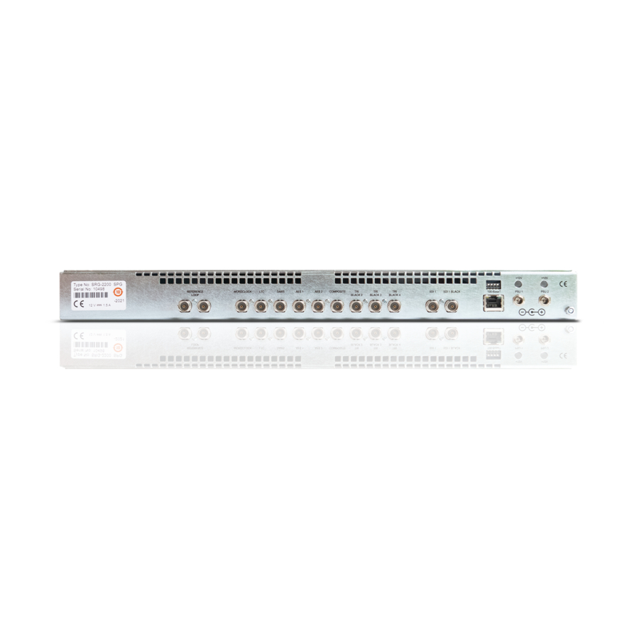
Hardware Overview This chapter outlines the front and rear panel features of the SRG-2200. Front Panel Overview Figure 3.1 shows the SRG-2200 Front Panel. Descriptions of the Front Panel controls and indicators appear below. SRG-2200 SYNC GENERATOR FAULT 1 2 3 4 SPG-2200 10.xx.xx.xx... - Page 16 If the SRG-2200 is to be used as a Master reference (i.e. not Genlocked), you do not have to supply a signal, and you may leave these BNCs unconnected. However, it is always wise to add a termination onto one BNC of an unused looping pair, in order to avoid having a “floating”...
-
Page 17: Physical Installation
2. Remove the instrument from the shipping carton. 3. Check that the SRG-2200 has not been damaged in transit. The exterior should not have any scratches or impact marks. Prior to shipment the SRG-2200 is thoroughly inspected for mechanical defects. -
Page 18: Rack Mount Installation
Rack Mount Installation You can install the SRG-2200 into an equipment rack. It is recommended to use the rack mount kit and to loom the cables so that they do not introduce extra weight or twisting force on the front panel rack mountings or rear panel connectors. -
Page 19: Connecting Power
Connecting Power The SRG-2200 operates from an externally supplied +12V DC power source. A safety earth stud is provided for earth bonding the chassis if you so require. Your SRG-2200 includes 2 external +12V power supply block to provide you will full redundancy. Note that you need to provide two power connections. -
Page 20: Accessories And Options
Accessories and Options This section lists the standard accessories that ship with the SRG-2200 and the available software options that you can purchase. Standard Accessories The following accessories are shipped with the SRG-2200. User Documentation Disc A Documentation Resources disc was included with your SRG-2200. -
Page 21: Functional Check Procedures
Functional Check Procedures Perform the following procedures if you are operating the SRG-2200 for the first time (to verify that the SRG-2200 shipped without damage), or you suspect that the SRG-2200 is not working properly. Required Equipment The following equipment is required for the functional check: •... -
Page 22: Initial Configuration
The New TCP openGear Frame Connection dialog opens. 2. Type the IP address of the SRG-2200 in the IP Address field. 3. Type a unique name for the SRG-2200 in the Display Name field. This name makes the SRG-2200 easily identifiable in the Tree View. -
Page 23: Check Outputs
5. Ensure that the SRG-2200 is displayed in the Tree View located on the left-side of the DashBoard window. Consult the DashBoard User Manual should the Tree View not display the SRG-2200. To access the SRG-2200 interfaces in DashBoard 1. From the Tree View, expand the node for the SRG-2200 you wish to configure. - Page 24 3. Connect the Black 1 video output to the Waveform / Picture Monitor using a 75ohm BNC cable. 4. Set the Waveform / Picture Monitor to view the Black 1 signal. 24 • Functional Check Procedures SRG-2200 User Guide (v6.0)
-
Page 25: Serial Digital Video Signal Outputs
SDI Embedded Audio Outputs Audio channels on the SDI outputs are arranged as 8 stereo pairs on each video output: • SDI 1 Pattern 01 … 16 • SDI 1 Black 01 … 16 SRG-2200 User Guide (v6.0) Functional Check Procedures • 25... -
Page 26: Aes / Ebu Audio Outputs
To verify the AES/EBU Audio Outputs 1. Double-click the Slot 5: Composite Video node. The Composite Video interface displays in the DashBoard window. 2. Select the AES Audio 1 & 2 tab. 26 • Functional Check Procedures SRG-2200 User Guide (v6.0) -
Page 27: Time And Timecode Settings
Full details regarding the setting of UTC Time, SPG Time, Summer & Winter DST Events, and Leap seconds can be found in section“Slot 12: System Time Tabs” on page 47. A flow chart outlining the Time and Date Configuration sequence is shown in Figure 6.2 in the same section. SRG-2200 User Guide (v6.0) Functional Check Procedures • 27... -
Page 28: Genlock Mode
Genlock Mode The Genlock tab allows the user to select the required Genlock mode of the SRG-2200. To verify the Genlock settings 1. -
Page 29: System Configuration
5. Check that < -Ref Status > confirms the instrument has not detected an external reference. 6. Using a 75ohm BNC cable, connect Color Black from the TV signal generator to the SRG-2200 REF-LOOP input BNC connector. Terminate the unused REF-LOOP connector with a 75ohm termination. -
Page 30: Network Settings
Network Settings The Network menu can be reached via the Slot16: System Setup tabs. This is where the IP Address and Subnet Mask of the SRG-2200 can be set and monitored in conjunction with the DIP Switches (on the rear panel). -
Page 31: Operational Configuration
Operational Configuration There are several configuration factors that will influence the initial installation of your SRG-2200, namely: • Mains Power • DC Power • Time, Date, DST etc. • Video and Audio outputs • References (Genlock, NTP, etc.) • Network •... - Page 32 32 • Functional Check Procedures SRG-2200 User Guide (v6.0)
-
Page 33: Dashboard Menus
SRG-2200. Events Tab The Event tab provides access to the last 99 events recorded by the SRG-2200. These events may relate to normal expected functionality or to systemic errors. This information might be useful in monitoring and diagnosing a system problem outside the SRG-2200, or a reliability problem within the SRG-2200. -
Page 34: Genlock Tab
+3v3 Regulator 42 45 41 Depending on the exact configuration and options in the SRG-2200, only those sensors that are detected will be displayed. If a sensor is installed but has failed, the description in the relevant line appears as:... - Page 35 Alternatively, the SRG-2200 can Genlock to an NTSC, or PAL B/G video reference. In this mode, the long term stability is defined by the external reference. When locked to a Composite video signal, the lock will be frequency and phase related.
-
Page 36: Psu Status Tab
Genlock Mode This tab allows the user to select the required Genlock mode of the SRG-2200. The options in the field are: • Internal to Free-run • Genlock to Video • Genlock to Video + VITC Genlock Loss of Video Reference This menu allows the user to select the action the SRG-2200 will take if reference is lost. -
Page 37: Sdi 1 Pattern & Ident Tab
Set the opacity of the Ident text, or turn it off Ident Row Motion Set the type of Ident text row motion Ident Box Motion Sets the type of Ident text box motion SRG-2200 User Guide (v6.0) DashBoard Menus • 37... -
Page 38: Sdi 1 Modifiers Tab
Allows the user to select the time code that will be inserted into the SDI 2 output For SD SDI, allows the user to turn on and off the embedded CRC checksums 38 • DashBoard Menus SRG-2200 User Guide (v6.0) -
Page 39: Sdi 1 Source Id Tab
SDI 1 Pattern - Embedded Audio 1-16 Tab Table 6.7 SDI 1 Pattern - Embedded Audio 1-16 Items Item Parameter Notes HD Pattern Embedder Audio 1...4 Audio 1...8 Audio 1...12 Audio 1...16 Embedded Tone Silence Channel - # SRG-2200 User Guide (v6.0) DashBoard Menus • 39... - Page 40 Blits can only be selected on channel 01. Blits also Glits uses the next five channels to create a 5.1 Surround Blits 5.1 Sound Audio Identification sequence. dBFS Silence -24 to -18dB 40 • DashBoard Menus SRG-2200 User Guide (v6.0)
-
Page 41: Sdi 1 Black - Embedded Audio 1-16 Tab
Select Slot5: Composite Video to Set, Select and configure the SD Analog Video to suit your requirements. The following Tabs are available to allow configuration of format, pattern, Text Idents, Embedded Audio and more. Figure 6.4 Example of Slot 5: Composite Video Tabs SRG-2200 User Guide (v6.0) DashBoard Menus • 41... -
Page 42: Composite Video Parameters
The vertical position of the on screen Ident text Character Size The size of the Ident text Iden Vis Chars Normally set to automatic, this allows the user to specify how many characters per Ident line are visible 42 • DashBoard Menus SRG-2200 User Guide (v6.0) -
Page 43: Composite Modifiers
Allows the user to turn on or off the on screen time and date display OSD Warnings If turned on, any warnings will be shown on the On Screen Display Composite Output Modifiers On Screen Menus VITC Line F1 / L10 SMPTE 318M SRG-2200 User Guide (v6.0) DashBoard Menus • 43... -
Page 44: Composite Timecode
C-Major chord (from the Harmonic Scale): 1056Hz = C, 1187Hz = D, 1319Hz = E, 1407Hz = F, 1584Hz = G, 1760Hz = A, 1979Hz = B, and 2112Hz = C Spot Frequency Sample 1 44 • DashBoard Menus SRG-2200 User Guide (v6.0) -
Page 45: Slots 8, 9, 10: Color Black And Tri-Level Sync Tabs
Select Slots 8,9,10: Color Black Set, Select and configure the format wand other parameters of the analog reference outputs to suit your requirements. The following Tabs are available to allow comprehensive configuration of format, modifiers, Timecode, and signal Timing Offsets. SRG-2200 User Guide (v6.0) DashBoard Menus • 45... -
Page 46: Triblack Video Parameters Tab
The number of ticks in once cycle of sub-carrier of the current video format. The range of values is 0 up to the total number of sub-pixels that equate to one cycle of sub-carrier in the selected format. 46 • DashBoard Menus SRG-2200 User Guide (v6.0) -
Page 47: Triblack Modifiers Tab
(DST Active?) Slot 12: System Time Tabs Select Slot12: System Time to configure and view all possible time outputs from the SRG-2200 to suit your location and application. The following tabs are available to allow comprehensive configuration and monitoring. SRG-2200 User Guide (v6.0) -
Page 48: Analog Ref Vitc Tab
• Date — The day of the month as reported by the NTP client. • Month — The month as reported by the NTP client. • Year — The year as reported by the NTP client. 48 • DashBoard Menus SRG-2200 User Guide (v6.0) -
Page 49: Ltc 1 Time Tab
” is used to add / subtract time in the UTC DateTime menu. The sub- fields in 00:00:00:00 the field “ ” represent hours : minutes : seconds : frames. When sub- fields are adjusted, the 00:00:00:00 corresponding fields in Running Time reflect the changes. SRG-2200 User Guide (v6.0) DashBoard Menus • 49... -
Page 50: Summertime Tab
If you select User Defined, then the time and date will automatically adjust at the time and date set in the Leap Second Event (UTC) menu. View All Times Tab This tab allows the user to see all the times being generated by the SRG-2200. Adjustments can be made per the above descriptions. 50 • DashBoard Menus... -
Page 51: Slot 16: System Setup Tabs
Figure 6.7 Example of Slot 16: System Setup Tabs Configuration Tab The Configuration tab provides access to a range of features that determine the functionality of the SRG-2200 not otherwise covered by other menu settings. These options are typically set up during the system commissioning of the SRG-2200, and thereafter are unlikely to be changed. -
Page 52: Network Tab
Displays the Network settings including the SRG-2200 IP address. • IP address of this SPG — This field allows the user to enter the IP address of the SRG-2200. The options in the sub-fields “000” are: 000 through 255 where 000" is the default “no action” setting. -
Page 53: Options Tab
This is the Primary/Backup SRG Tab This tab appears if the SRG-2200 is set as the Primary unit in a Changeover pair. It informs the user that the SRG-2200 is the Primary unit of a Changeover pair, and consequently, polling (of the remote device) is disabled. -
Page 54: Calibration Tab
SRG-2200. Keys will not work for other options on the same SRG-2200, nor on any other SRG-2200. Remember to store these keys in a safe place - you may need to re-enter them if a system error necessitates a system re-configuration. -
Page 55: Upgrading The Software
1. Ensure that the SRG-2200 is powered on. 2. On your PC, run the RossSystemUpdate_v#.#.#.#.exe program. 3. Set the IP address and IP Mask to be the same as that of the SRG-2200 itself. 4. Select the button. The status window should confirm the mode: Get Mode “... - Page 56 , check again that all connections have been made, then try repeating the not found” above procedure after powering down the SRG-2200, and then resuming from the update program start-up line. 5. If the SRG-2200 still cannot be found, contact Ross Video for further assistance.
-
Page 57: Troubleshooting
Key(s) Rebooting the NTP Sub-system The following tabs in DashBoard provide a button that can be used to reboot the sub-systems of the SRG-2200: • Slot 0: SRG-2200 > Genlock > Do NTP Reboot • Slot 16: System Setup > Network > NTP > Do NTP Reboot Equipment Checklist Routine maintenance to this Ross Video product is not required. -
Page 58: Contacting Ross Video Technical Support
Contact Ross Video for further assistance. When you contact Ross Video regarding an issue on your SRG-2200, and so that we can process your inquiry efficiently, you should have available at least one of the following items of information in addition to your personal / company details (name, company, telephone, email): •... -
Page 59: Specifications
65. • The SRG-2200 must have a warm-up period of at least 20 minutes. • The SRG-2200 must have been calibrated and adjusted at an ambient temperature between +20°C and +30°C at an altitude of less than 2000m. • The following label is used to indicated the altitude limitation. -
Page 60: Video Reference Inputs
Input Requirements Amplitude -6dB to +6dB S/N Ratio >40dB ScH Phase ±20° Pull-in Range ±50ppm Jitter Burst <0.5° Sync <1ns Genlock Time Offset Range Range Full color range Resolution <0.5 degree of sub-carrier 60 • Specifications SRG-2200 User Guide (v6.0) -
Page 61: Analog Video Outputs
› Line 263 and Line 283 are specified as active half lines in SMPTE RS170M but they are fully blanked in this SRG-2200. Composite Output: PAL • Field 1 lines 623 - 23 inclusive are blanked i.e. there is no pattern information but there may be VITC etc. SRG-2200 User Guide (v6.0) Specifications • 61... -
Page 62: Serial Digital Interface
270Mbps Timing: <=0.16UI <0.2UI @ 10Hz Alignment: <=0.10UI <0.2UI @ 1KHz 1.5Gbps Timing: <=0.30UI <1.0UI @ 10Hz Alignment: <=0.07UI <0.2UI @ 100KHz 3Gbps Timing: <=0.65UI <2.0UI @ 10Hz Alignment: <=0.15UI <0.3UI @ 100KHz 62 • Specifications SRG-2200 User Guide (v6.0) -
Page 63: Aes/Ebu Audio Unbalanced Outputs Specifications
Typically 2ns Audio Parameters Frequency 1Hz-20kHz Steps of <1Hz Amplitude Silence and -78dBFS to 1dB resolution 0dBFS Pre-emphasis None Interruption Programmable 1 second, 3 second, EBU TECH 3304, Glits, Blits Quantized Resolution 24bits SRG-2200 User Guide (v6.0) Specifications • 63... -
Page 64: Ltc Output
< 10 broadcast and/or multicast messages per second. Table 9.7 Ethernet Interface Category Performance Requirement Reference Information Connector Type 1 x RJ45 - 8P8C IEEE Standards Compliance IEEE 802.3i-1990 10BASE-T IEEE 802.3u-1995 100BASE-TX 64 • Specifications SRG-2200 User Guide (v6.0) -
Page 65: Physical Specifications
To 12,192m (40,000ft) Vibration Operating 2.65m/s2 (0.27Grms), 5Hz to 500Hz, 10 minutes per axis, three axes Non-operating 22.3m/s2 (2.28Grms), 5Hz to 500Hz, 10 minutes per axes, three axes Shock Non-operating 294m/s2 (30G), half-sine, 11ms duration SRG-2200 User Guide (v6.0) Specifications • 65... - Page 66 66 • Specifications SRG-2200 User Guide (v6.0)
-
Page 67: Certifications And Compliances
Complies with the EMC Framework, demonstrated per Emission Standard Declaration of AS/NZS 2064 (Industrial, Scientific, and Medical Equipment). Conformity -EMC Safety Complies with the following safety standards: UL 60950-1, 2nd Edition CSA C22.2 No. 60950-1-07 EN 60950-1:2006/A2:2013 IEC 60950-1:2005/A2:2013 SRG-2200 User Guide (v6.0) Certifications and Compliances • 67... - Page 68 • Installation Category II (Single-phase, receptacle Type: Test and -connected loads) Measuring • Pollution Degree 2 (Normally only non-conductive pollution occurs) • Safety Class I (Grounded product) • Temperature 5°C to 40°C 68 • Certifications and Compliances SRG-2200 User Guide (v6.0)
-
Page 69: Characters For Idents
Table 11.1 lists the supported characters. Unsupported characters are set in grey. Generally, if an unsupported character is detected, it will be replaced with the ‘space’ character 0x20. Table 11.1 Available Characters for Idents 000-007 ‘ “ & SRG-2200 User Guide (v6.0) Characters for Idents • 69... - Page 70 ò £ ³ Ã Ó ã ó ¤ ´ Ä Ô ä ô ¥ µ Å Õ å õ ¦ ¶ Æ Ö æ ö § · Ç × ç ÷ 70 • Characters for Idents SRG-2200 User Guide (v6.0)
- Page 71 ê ú « » Ë Û ë û ¬ ¼ Ì Ü ì ü ½ Í Ý í ý ® ¾ Î Þ î þ ¯ ¿ Ï ß ï ÿ SRG-2200 User Guide (v6.0) Characters for Idents • 71...
- Page 72 72 • Characters for Idents SRG-2200 User Guide (v6.0)
-
Page 73: Test Patterns
Test Patterns This chapter provides an overview of the test patterns available for the SRG-2200. The patterns are stored in a pattern file in FLASH memory. The pattern file can be updated via the Ethernet interface. A slightly different set of test patterns is available for each signal format. - Page 74 //46 "sweep_Full_Mono ", "sweep_Half_Mono ", //48 "sweep_Half_Luma_Full_Chroma ", "sweep_Half_Luma_Half_Chroma ", "100%_valid_ramps_1 ", "Luma_ramp_full_width_1 ", "Cb_ramp_full_width_1 ", //53 "Cr_ramp_full_width_1 ", //54 "All_ramps_full_width_1 ", //55 "Field_Sequence0_F0_to_F3 ", //56 "Field_Sequence1_F1_to_F4 ", "Sinxx_Pulses ", "7_T_Pulses ", 74 • Test Patterns SRG-2200 User Guide (v6.0)
-
Page 75: 625I Test Patterns
", //26 "bar095_9 ", //27 "bar095_9_red095 ", //28 "bar095_8 ", //29 "bar095_8_red095 ", //30 "bar075_9 ", //31 "bar075_9_red075 ", //32 "bar075_8 ", //33 "bar075_8_red075 ", //34 "barebu_9 ", //35 "barebu_9_red075 ", //36 SRG-2200 User Guide (v6.0) Test Patterns • 75... - Page 76 //46 "sweep_Full_Mono ", //47 "sweep_Half_Mono ", //48 "sweep_Half_Luma_Full_Chroma ", //49 "sweep_Half_Luma_Half_Chroma ", //50 "100%_valid_ramps_1 ", //51 "Luma_ramp_full_width_1 ", "Cb_ramp_full_width_1 ", "Cr_ramp_full_width_1 ", "All_ramps_full_width_1 ", "Field_Sequence0_F0_to_F7 ", "Field_Sequence1_F1_to_F8 ", "Sinxx_Pulses ", "7_T_Pulses ", 76 • Test Patterns SRG-2200 User Guide (v6.0)
-
Page 77: 720P Test Patterns
"bar100_8 ", "bar100_8_red075 ", "bar095_9 ", "bar095_9_red075 ", "bar095_8 ", "bar095_8_red075 ", "bar075_9 ", "bar075_9_red075 ", "bar075_8 ", "bar075_8_red075 ", "barebu_9 ", "barebu_9_red075 ", "barebu_8 ", "barebu_8_red075 ", "pathalogical_frame0 ", "pathalogical_frame1 ", SRG-2200 User Guide (v6.0) Test Patterns • 77... - Page 78 "multiburst_full_mono ", "multiburst_half_mono ", "multiburst_Half_Luma_Full_Chro", "multiburst_half_color ", "sweep_full_mono ", "sweep_half_mono ", "sweep_Half_Luma_Full_Chroma ", "sweep_half_color ", "100%_valid_ramps_1 ", //45 "100%_valid_ramps_2 ", //46 "7_T_Pulses ", //47 78 • Test Patterns SRG-2200 User Guide (v6.0)
-
Page 79: 1035I Test Patterns
"bar095_9 ", "bar095_9_red075 ", "bar095_8 ", "bar095_8_red075 ", "bar075_9 ", "bar075_9_red075 ", "bar075_8 ", "bar075_8_red075 ", "barebu_9 ", "barebu_9_red075 ", "barebu_8 ", "barebu_8_red075 ", "pathalogical_frame0 ", "pathalogical_frame1 ", "multiburst_full_mono ", "multiburst_half_mono ", SRG-2200 User Guide (v6.0) Test Patterns • 79... - Page 80 "multiburst_Half_Luma_Full_Chro", "multiburst_half_color ", "sweep_full_mono ", "sweep_half_mono ", "sweep_Half_Luma_Full_Chroma ", "sweep_half_color ", "100%_valid_ramps_1 ", "100%_valid_ramps_2 ", "7_T_Pulses ", //45 80 • Test Patterns SRG-2200 User Guide (v6.0)
-
Page 81: 1080I And 1080Psf Test Patterns
", //26 "bar075_9 ", //27 "bar075_9_red075 ", //28 "bar075_8 ", //29 "bar075_8_red075 ", //30 "barebu_9 ", //31 "barebu_9_red075 ", //32 "barebu_8 ", //33 "barebu_8_red075 ", //34 "pathalogical_frame0 ", //35 "pathalogical_frame1 ", //36 SRG-2200 User Guide (v6.0) Test Patterns • 81... - Page 82 "multiburst_full_mono ", //37 "multiburst_half_mono ", //38 "multiburst_Half_Luma_Full_Chro", //39 "multiburst_half_color ", //40 "sweep_full_mono ", //41 "sweep_half_mono ", //42 "sweep_Half_Luma_Full_Chroma ", //43 "sweep_half_color ", //44 "100%_valid_ramps_1 ", //45 "100%_valid_ramps_2 ", //46 "7_T_Pulses ", //47 82 • Test Patterns SRG-2200 User Guide (v6.0)
-
Page 83: 1080P Test Patterns
", //26 "bar075_9 ", //27 "bar075_9_red075 ", //28 "bar075_8 ", //29 "bar075_8_red075 ", //30 "barebu_9 ", //31 "barebu_9_red075 ", //32 "barebu_8 ", //33 "barebu_8_red075 ", //34 "pathalogical_frame0 ", //35 "pathalogical_frame1 ", //36 SRG-2200 User Guide (v6.0) Test Patterns • 83... - Page 84 "multiburst_full_mono ", //37 "multiburst_half_mono ", //38 "multiburst_Half_Luma_Full_Chro", //39 "multiburst_half_color ", //40 "sweep_full_mono ", //41 "sweep_half_mono ", //42 "sweep_Half_Luma_Full_Chroma ", //43 "sweep_half_color ", //44 "100%_valid_ramps_1 ", //45 "100%_valid_ramps_2 ", //46 "7_T_Pulses ", //47 84 • Test Patterns SRG-2200 User Guide (v6.0)
-
Page 85: Ntp Option
• Once the time-code has been set by the NTP Client, the SRG-2200 should not need to re-check the NTP time unless a crash lock has been forced by the phase locking arrangement. -
Page 86: Simplified Ntp Flowcharts
Is the Measured Time Delay < Threshold? Is the GPS Solution Is the NTP Lock set to Locked? Lock SRG-2200 to NTP and Set NTP Lock to Locked Figure 13.1 NTP Client Flowchart 86 • NTP Option SRG-2200 User Guide (v6.0) -
Page 87: Required Time Corrections
Required Time Corrections From an NTP Server, the SRG-2200 Master Clock can derive UTC and also add the appropriate time offset and provide corrected local time. Table 13.1 contains a list of the various corrections which need to be made by the SRG-2200. - Page 88 88 • NTP Option SRG-2200 User Guide (v6.0)
-
Page 89: Date In The User Bits Of Timecode
Date in the User Bits of Timecode This chapter provide an overview of how the SRG-2200 inserts and reads the user bits in time code to decode date and time zone information. The SRG-2200 supports two methods of date information in the user bits of LTC and VITC: •... - Page 90 Optional Time Zone - 3 Optional Time Zone - 4 Optional Time Zone - 5 Year 10s of units Reserved - set to 0 YYMMDD Format = 0 90 • Date in the User Bits of Timecode SRG-2200 User Guide (v6.0)
-
Page 91: Service Information
Service Information This chapter contains procedures for cleaning and performing preventive maintenance on the SRG-2200, general servicing information, and the warranty policies. User Maintenance This section contains information for cleaning and performing preventive maintenance on the SRG-2200. General Care Protect the instrument from adverse conditions, i.e. high humidity, high temperatures, etc. The instrument is NOT waterproof. -
Page 92: Servicing
If your problem cannot be resolved, contact Ross Video for further advice. If you ordered a Service Option, then removing the unit from the bay and returning it to Ross Video for updating will provide the user with the opportunity to inspect the unit for any problems relating to the operating conditions/environment. - Page 93 This SRG-2200 User Manual provides all pertinent information for the safe installation and operation of your Ross Video Product. Ross Video policy dictates that all repairs to the SRG-2200 are to be conducted only by an authorized Ross Video Limited factory representative. Therefore, any unauthorized attempt to repair this product, by anyone other than an authorized Ross Video Limited factory representative, will automatically void the warranty.
- Page 94 94 • Service Information SRG-2200 User Guide (v6.0)
-
Page 95: Glossary
• “GLONASS” refers to the Global Navigation Satellite System. • “GPS” refers to global positioning system. • “Operator” and “User” refer to the person who uses SRG-2200. • “RF interference” refers to radio frequency interference. • “System” and “Video system” refer to the mix of interconnected production and terminal equipment in your environment. - Page 96 96 • Glossary SRG-2200 User Guide (v6.0)
Need help?
Do you have a question about the SRG-2200 and is the answer not in the manual?
Questions and answers