Table of Contents
Advertisement
Quick Links
Advertisement
Table of Contents

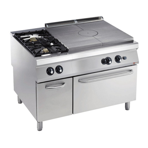
Summary of Contents for Diamond G22/T2BFA12-AGA
- Page 1 04/2016 Mod: G22/T2BFA12-AGA Production code: 393265...
-
Page 2: Table Of Contents
CONTENTS I. JOINING APPLIANCES / TABLES ....................2 II. DATAPLATE and TECHNICAL DATA ....................15 III. GENERAL INSTRUCTIONS ......................16 IV. THE ENVIRONMENT ......................... 17 1. PACKING ............................17 2. USE ............................. 17 3. CLEANING ............................17 4. DISPOSAL ............................17 V. -
Page 3: Dataplate And Technical Data
II. DATAPLATE and TECHNICAL DATA ATTENTION This manual contains instructions relevant to various appliances. See the dataplate located under the control panel to identify the appliance (see fig. above). TABLE A - Gas appliance technical data MODELS +9STGH1000 +9STGH10G0 +9STGL3010 +9STGH30G0 800mm 800mm... -
Page 4: General Instructions
III. GENERAL INSTRUCTIONS • Read the instruction manual carefully before using the appliance. • Keep the instruction manual for future reference.. • RISK OF FIRE - Keep the area around the appliance free and clear of combustibles. Do not keep flammable materials in the vicinity of this appliance. -
Page 5: The Environment
IV. THE ENVIRONMENT V. INSTALLATION • Carefully read the installation and maintenance 1. PACKING procedures given in this instruction manual before The packing materials are environmentally installing the appliance. friendly and can be stored without risk or burned • Installation, maintenance and conversion to another type in an appropriate waste incineration plant. -
Page 6: Fume Exhaust And Ventilation
• Leave an adequate space between the appliance and any 4.2.1 CONNECTION FLUE side walls in order to enable subsequent servicing or • Remove the grille from the fume exhaust. maintenance operations. • Install the connection flue, following the instructions •... -
Page 7: Connections
5.1.4 GAS PRESSURE REGULATOR 5. CONNECTIONS If the gas pressure is higher than that specified or is difficult • Any installation work or maintenance to the to regulate (not stable), install a gas pressure regulator supply system (gas, electricity, water) must only (accessory code 927225) in an easily accessed position be carried out by the utility company or an ahead of the appliance. -
Page 8: Before Completing Installation Operations
5.1.6.1 SOLID TOP and COOKTOP MAIN BURNER NOZZLE REPLACEMENT (simple service version) • Unscrew nozzle “C” and replace it with one suitable for the type of gas (Table B, fig.3A, 3C) according to that given in the following table. • The nozzle diameter is given in hundredths of mm on the nozzle body. -
Page 9: Instructions For The User
NOTE: VI. INSTRUCTIONS FOR THE During use, the hottest part of the hot-plate (in cast iron) is in the middle. USER 1. SOLID TOP USE General precautions • The appliance is intended for industrial use by trained personnel. • Avoid using the appliance empty for long periods or in conditions that compromise optimal efficiency. -
Page 10: Oven Use
3. OVEN USE VII. CLEANING Switching on The thermostatic valve control knob has the following positions: IMPORTANT! Disconnect the appliance from the power supply before carrying out any cleaning. “Off” “Pilot ignition” 1. EXTERNAL PARTS “Pilot” SATIN-FINISH STEEL SURFACES (daily) “Burner”... -
Page 11: Maintenance
VIII. MAINTENANCE 1. MAINTENANCE All components requiring maintenance are accessible from the front of the appliance, after removing the control panel and front panel. Disconnect the power supply before opening the appliance 1.1 BRIEF TROUBLESHOOTING GUIDE Even with normal use, malfunctions can occur. - The pilot burner of open burners does not light Possible causes: •...


Need help?
Do you have a question about the G22/T2BFA12-AGA and is the answer not in the manual?
Questions and answers