
Related Manuals for AR 350AH1A


Summary of Contents for AR 350AH1A
- Page 1 Operating and Service Manual 350AH1A Model 10042958 Part Number Serial Number 160 School House Road, Souderton, PA 18964 • 215-723-8181 • Fax 866-859-0582 • www.arworld.us...
- Page 3 OF THE EUROPEAN PARLIAMENT AND OF THE COUNCIL of 18 December 2006 concerning the Registration, Evaluation, Authorization and Restriction of Substances of Very High Concern Chemicals (SVHC) Supporting documentation is held by AR RF/Microwave Instrumentation’s Quality department in Pennsylvania, United States. Place of issue:...
- Page 5 The caution symbol denotes a potential hazard. Attention must be given to the statement to prevent Your AR equipment may have more than one power supply cable. Use damage, destruction, or harm. only approved power cable(s). If you have not been provided with a Dangerous voltages are present.
- Page 6 EQUIPMENT CONTAINING LASERS risk of serious injury due to unsafe AR Field Probes (FL/PL Series) and Field Analyzers (FA product handling should be a fundamental Series) are Class 1 laser products containing embedded consideration every user.
- Page 7 Zur Vermeidung von Personen- oder Sachschäden gilt BEVOR SIE DAS GERÄT ANSCHLIESSEN es, die Hinweise zu beachten. Ihre AR-Ausrüstung hat möglicherweise mehr als ein Stromversorgungskabel. Gefährliche elektrische Spannungen sind vorhanden. Verwenden Sie nur zugelassene Stromkabel. Falls Sie kein Stromkabel oder Höchste Vorsicht ist geboten.
- Page 8 Die meisten Geräte müssen während des Versands, der Montage und des Gebrauchs LASER-INFORMATION transportiert werden. Jeder Nutzer sollte sich AR - Feldsonden (FL/PL-Serie) und Feldanalysatoren (FA-Serie) über das Risiko von schweren Verletzungen sind Laserprodukte der Klasse 1 mit eingebetteten Klasse-4- durch unsachgemäße...
- Page 9 électrode de mise à la Votre équipement AR peut disposer de plus d’un câble d’alimentation terre de protection. électrique. Utilisez uniquement un ou des câbles d’alimentation approuves.
- Page 10 éliminer le risque injustifié de blessures causées par le levage est fournie par les méthodes de travail de NIOSH (publication Les sondes de champ AR (série FL/PL) et les analyseurs de n° 94-110) disponibles sur : champ (série FA) sont des produits laser de classe 1 contenant des lasers intégrés de classe 4.
- Page 11 Er zijn gevaarlijke elektrische spanningen aanwezig. Wees uiterst voorzichtig. VOOR HET OPZETTEN VAN DE STROOM Uw AR-apparatuur kan meer dan een netvoedingskabel bezitten. Gebruik alleen goedgekeurde netvoedingskabel(s). Koopt een Wijst op een terminal aan die bedoeld is voor aansluiting netvoedingskabel die is goedgekeurd voor gebruik in uw land als u...
- Page 12 APPARAAT DAT LASERS BEVAT distributie, de assemblage en het gebruik moeten worden behandeld, moet het risico AR-terreinsondes (FL/PL-serie) en terreinanalysatoren (FA- op ernstig letsel als gevolg van een serie) zijn laserproducten van klasse 1 met ingesloten onveilige behandeling van het product een klasse 4-lasers.
-
Page 13: Addendum
ADDENDUM This amplifier may contain assemblies fabricated using both leaded and lead-free solders. These solders are not compatible with one another and care must be taken to use the appropriate process when repairing these assemblies. All assemblies in this unit that were assembled using a lead-free process are identified on the PCB using the lead-free symbol shown at right. -
Page 15: Table Of Contents
TABLE OF CONTENTS ADDENDUM ........................i TABLE OF CONTENTS ....................i GENERAL INFORMATION ................1 General Description ....................1 Specifications ......................1 Power Supplies ...................... 2 Protection Circuits ....................2 Installation ......................2 1.5.1 Location ......................... 2 1.5.2 AC Power ....................... 3 Connectors ...................... - Page 16 Model 350AH1A Amplifier ......................27 3.2.1 Amplifier RF Input ....................27 3.2.2 Variable Gain Amp ....................27 3.2.3 350W Module ....................... 27 Power Supply ....................... 27 Control Circuits ....................28 3.4.1 Power On/Operate Circuits .................. 28 3.4.2 A13 ALC Board (Schematic #10023927) ............28 Fault Detection Circuits..................
-
Page 17: General Information
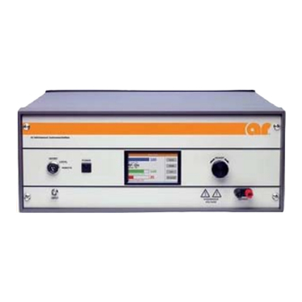
The Model 350AH1A, when used with a RF sweep generator, will provide up to 350 watts of swept power covering the frequency range from 10kHz to 1MHz. The Model 350AH1A is housed in a single stylish contemporary equipment cabinet. -
Page 18: Power Supplies
Select an operating location that will permit free air circulation around the amplifier’s cabinet. The Model 350AH1A utilizes air cooling and should be located where the normal flow of air into or exiting from the unit will not be restricted, diverted, or re-circulated through the unit itself. For example, do not position the unit next to a wall or other equipment that would cause a restriction of airflow into or out of the unit. -
Page 19: Ac Power
Model 350AH1A 1.5.2 AC Power The Model 350AH1A is designed for a primary power input of 90–260 VAC, 47/63 Hz, single phase. CAUTION: Dangerous voltages are present in the amplifier whenever it is plugged into an AC outlet. Always disconnect the AC power line to the amplifier before servicing the unit. - Page 20 Model 350AH1A 1.6.4.4 Ethernet A standard RJ-45 connector is provided on the rear panel. Rev B...
- Page 21 When used with an RF sweep gener- normal operation when the condition has been 10Hz–1MHz ator, the 350AH1A will provide up to 350 cleared. The unit also includes digital control watts of output power. for both local and remote control of the ampli- fier.
- Page 22 50.3 x 19.9 x 37.6 cm 350AH1AM3 Front Panel 18.2 kg (40.0 lb) 48.3 x 17.8 x 37.6 cm To order AR Products, call 215.723.8181. For an applications engineer call:800.933.8181. Direct to Service call: 215.723.0275 or email: service@arworld.us For Faxing Orders:866.859.0582 (Orders Only Please) info@arworld.us...
-
Page 23: Operating Instructions
(either through direct connection or parasitic feedback paths) will cause oscillations that may permanently damage the unit’s input transistors. CONTROL AND INDICATOR FUNCTIONS The Model 350AH1A’s front panel is shown in Figure 2-1; the unit’s rear panel features are detailed in Figure 2-2. 2.2.1... -
Page 24: Main Power Circuit Breaker
Model 350AH1A Figure 2-1. Digital Control Panel (DCP) Features Item Title Function INHIBIT, LOCAL, REMOTE Keylock Switch, 3-position; key removal in INHIBIT position only POWER POWER control with indicator LED DISPLAY Numerous parameter values and fault messages ADJUST Adjust knob to change selected variables 2.2.3... -
Page 25: Rf On/Off
Model 350AH1A 2.2.4 RF ON/OFF The RF ON/OFF touch screen button toggles the amplifier from a Standby to an Operate mode. The status of the function is indicated on the display as RF ON or RF OFF. In the RF ON state, RF output is enabled according to control settings and amplifier RF input. -
Page 26: Amplifier Operating Mode
This mode provides no automatic control of the amplifier’s RF output level other than that provided by the amplifier’s protective circuitry. 2.3.2 Adjusting Amplifier Controls All adjustments to control the operation of the Model 350AH1A are made using the dedicated controls, display menus and adjust knob functionality. 2.3.2.1 RF GAIN Control The RF GAIN control, which has a minimum of 15dB of range, is used to adjust the gain of the variable gain module. -
Page 27: Inputs And Outputs
2.4.3 IEEE-488, USB, and RS-232 Interfaces The Model 350AH1A’s remote interfaces allow remote control, via a computer, of all amplifier functions (except for the Keylock Switch position) that can be controlled from the front panel. When the amplifier is in the Remote mode (as determined by the position of the Keylock Switch), a special Remote display is shown (see Figure 2-3). -
Page 28: Amplifier Operation
Model 350AH1A AMPLIFIER OPERATION 2.5.1 CW Mode This section describes how a single 350AH1A amplifier would be used in CW mode. A block diagram of a typical set-up is shown in Figure 2-4, Typical Setup–CW Mode. Phase=0 350AH1 350AH1A Load Figure 2-4. -
Page 29: Bridge Mode
2.5.2 Bridge Mode This section describes how a pair of 350AH1A amplifiers may be used in a bridge configuration. The bridged configuration allows for a larger voltage swing than possible with a single amplifier by inverting the second amplifier and connecting the load between the two outputs. A block diagram of a typical set-up is shown in Figure 2-5, Typical Setup–Bridge Mode. -
Page 30: Parallel Mode
2.5.3 Parallel Mode This section describes how a pair of 350AH1A amplifiers may be used in a parallel configuration. A parallel configuration allows for more current to be delivered into a common load by using two or more amplifiers operating together in phase. A block diagram of a typical set-up is shown in Figure 2-6, Typical Setup–... -
Page 31: Remote Communications
Communicating through two or more ports at one time will cause data collisions and lost commands or queries. The Keylock switch on the control panel of the model 350AH1A allows it to be controlled using remote communications. All remote queries will work in any Keylock switch position, but all remote commands will only work when the position is set to REMOTE. -
Page 32: Rs-232 Communications
Model 350AH1A 2.6.2 RS-232 Communications The RS-232 port is a serial communications bus. All commands and queries through this port must be terminated with a Line Feed character. When a valid query is received, it is processed and the result is immediately transmitted back over the RS-232 interface. -
Page 33: Usb Communications
This port can be used in conjunction with either an AR model IF7000 RS-232 to Fiber-Optic Interface (1200 to 9600 baud only) or an AR model IF7001 USB to Fiber-Optic Interface (19200 baud only). Note that these devices use SMA connectors so a fiber-optic cable is needed with ST connectors on one end and SMA connectors on the other. -
Page 34: Remote Commands
Lantronix Ethernet devices. This list of found devices will include any connected AR Ethernet devices. By selecting one of the connected devices from the list, its IP address and subnet mask can be changed along with a number of other settings. -
Page 35: Relationships Between Amplifier Controls And Responses
Model 350AH1A Table 2-4. Relationship between Amplifier Controls and Responses X=NO, √=YES AC POWER AND POWER KEYLOCK SWITCH REMOTE CIRCUIT BREAKER COMMUNICATION INHIBIT LOCAL REMOTE COMMAND QUERY √ √ √ √ √ √ √ √ √ √ √ √ √... - Page 36 Model 350AH1A 2.6.6.3 Reset Faults This will clear all faults, if possible. Syntax: RESET Parameters: None Response Format: None (No query for this command) To clear any faults, send the following command: RESET<LF> Example: 2.6.6.4 Level Adjust This command sets the RF Gain of the amplifier.
- Page 37 Model 350AH1A Example: identity amplifier, send following command: *IDN?<LF> Response: AR-RF/MICROWAVE-INST,350AH1A,1.0<LF> 2.6.6.6 IO Board Firmware Revision Query to get the firmware revision of the IO Board. Syntax: *IOB? Parameters: None Query only (always requires a ? character) Response Format: INTERFACE_BOARD_SW_REVx<LF>...
- Page 38 Model 350AH1A BIT STATE BIT DESCRIPTION NOTES: POSITION (NOT USED) (NOT USED) (NOT USED) REMOTE CONTROL DISABLED ENABLED Response to key-switch position POWER STATUS POWER ON STANDBY STATUS STANDBY Also known as RF OFF OPERATE STATUS OPERATE Also known as RF ON...
- Page 39 Model 350AH1A 2.6.6.9 RMS Current Query to get the RMS output current. Syntax: IRMS? Parameters: None Response Format: IRMS=x Where: x = 0.0 to 99.9 Values are corrected and linearized. They can be up to four characters in length. Each response contains one decimal point that counts as one of the four characters.
- Page 40 Model 350AH1A 2.6.6.11 RF Gain Query to get the RF gain. Syntax: RFG? Parameters: None Response Format: RFG=<space>x Where: x = 0000 to 0100 Example: To find out the RF gain of the amplifier, send the following query: RFG?<LF> Response: RFG=<space>...
- Page 41 Model 350AH1A 2.6.6.13 Output Measurement Display Mode Command to set the format used to display output measurements. Syntax: DISP:x Mode(x): Parameters: IVR = display RMS Voltage and RMS Current PWR = display RMS Power Response Format: None (No query for this command)
- Page 42 Model 350AH1A Rev B...
-
Page 43: Theory Of Operation
POWER SUPPLY Refer to Schematic Diagram Number 10024922, Interconnect Diagram, 350AH1A. Main power to the unit is supplied by single phase AC power within the proper range. In series with the line voltage is the 20A Main circuit breaker CB1, located on the rear panel. -
Page 44: Control Circuits
This section describes the functioning of the switches, relays and controls in the AC/DC power distribution system. See Schematic Drawing Number 10024922, Interconnect Diagram, 350AH1A. Circuit breaker CB1 disconnects all circuits from the AC mains. Assume that circuit breaker CB1 is closed. -
Page 45: Fault Detection Circuits
Thermal Faults The 350AH1A output module contains a thermal sensor switch. In the case of a thermal fault, the line will go high. The control panel displays TH, and the main power supply will be inhibited to allow the module to cool down. - Page 46 Model 350AH1A 3.5.4.2 AC Interlock For interlock applications that are more safety critical, where logic circuits are not trusted, the AC interlock can be used to disconnect the amplifier from the AC mains. This interlock circuit is connected directly in series with the AC relay circuit.
-
Page 47: Troubleshooting And Repair
4. TROUBLESHOOTING AND REPAIR 4.1. GENERAL Because it is a relatively simple instrument, the Model 350AH1A should require very little maintenance. It is built with solid state devices and printed wiring boards (PWBs) that should ensure long, trouble-free life. Should trouble occur, special care must be taken when servicing the unit to avoid damaging the solid-state devices and PWBs. -
Page 48: General - Reading Faults
4.2.1 General - Reading faults The Model 350AH1A incorporates relatively simple fault detection circuitry, which makes use of the digital display panel to alert the user or technician which component(s) need service. Use of these indications can usually expedite troubleshooting of the amplifier. Most faults can be immediately determined down to the assembly level. - Page 49 These modules are not field-repairable and should never be opened outside of AR’s Microelectronics Lab. The modules in these product lines have a security label on two sides of the modules between the housing and lid/cover. If the security label is removed and or cut, the warranty of the module will be voided.
Need help?
Do you have a question about the 350AH1A and is the answer not in the manual?
Questions and answers