
Related Manuals for AR 40T18G26A Series


Summary of Contents for AR 40T18G26A Series
- Page 1 Operating and Service Manual 40T18G26A Model 10010475 Part Number Serial Number 160 School House Road, Souderton, PA 18964 • 215-723-8181 • Fax 215-723-5688 • www.arworld.us...
- Page 3 Amplifier Research 160 School House Road Souderton, PA. 18964 declare that our product(s); the Model 40T18G26A series RF amplifiers to which this declaration relates is in compliance with the following European directives: Low Voltage Directive: 2014/35/EU EMC Directive: 2014/30/EU Supplementary Information:...
- Page 5 The caution symbol denotes a potential hazard. Attention must be given to the statement to prevent Your AR equipment may have more than one power supply cable. Use damage, destruction, or harm. only approved power cable(s). If you have not been provided with a Dangerous voltages are present.
- Page 6 EQUIPMENT CONTAINING LASERS risk of serious injury due to unsafe AR Field Probes (FL/PL Series) and Field Analyzers (FA product handling should be a fundamental Series) are Class 1 laser products containing embedded consideration every user.
- Page 7 Zur Vermeidung von Personen- oder Sachschäden gilt BEVOR SIE DAS GERÄT ANSCHLIESSEN es, die Hinweise zu beachten. Ihre AR-Ausrüstung hat möglicherweise mehr als ein Stromversorgungskabel. Gefährliche elektrische Spannungen sind vorhanden. Verwenden Sie nur zugelassene Stromkabel. Falls Sie kein Stromkabel oder Höchste Vorsicht ist geboten.
- Page 8 Die meisten Geräte müssen während des Versands, der Montage und des Gebrauchs LASER-INFORMATION transportiert werden. Jeder Nutzer sollte sich AR - Feldsonden (FL/PL-Serie) und Feldanalysatoren (FA-Serie) über das Risiko von schweren Verletzungen sind Laserprodukte der Klasse 1 mit eingebetteten Klasse-4- durch unsachgemäße...
- Page 9 électrode de mise à la Votre équipement AR peut disposer de plus d’un câble d’alimentation terre de protection. électrique. Utilisez uniquement un ou des câbles d’alimentation approuves.
- Page 10 éliminer le risque injustifié de blessures causées par le levage est fournie par les méthodes de travail de NIOSH (publication Les sondes de champ AR (série FL/PL) et les analyseurs de n° 94-110) disponibles sur : champ (série FA) sont des produits laser de classe 1 contenant des lasers intégrés de classe 4.
- Page 11 Er zijn gevaarlijke elektrische spanningen aanwezig. Wees uiterst voorzichtig. VOOR HET OPZETTEN VAN DE STROOM Uw AR-apparatuur kan meer dan een netvoedingskabel bezitten. Gebruik alleen goedgekeurde netvoedingskabel(s). Koopt een Wijst op een terminal aan die bedoeld is voor aansluiting netvoedingskabel die is goedgekeurd voor gebruik in uw land als u...
- Page 12 APPARAAT DAT LASERS BEVAT distributie, de assemblage en het gebruik moeten worden behandeld, moet het risico AR-terreinsondes (FL/PL-serie) en terreinanalysatoren (FA- op ernstig letsel als gevolg van een serie) zijn laserproducten van klasse 1 met ingesloten onveilige behandeling van het product een klasse 4-lasers.
- Page 13 ADDITIONAL WARNINGS & NOTES WARNING: This equipment operates at potentially lethal voltages. Only trained, qualified personnel should operate, maintain, or service it. Hazardous energy may be present while protective covers are removed from the equipment even if disconnected from the power source. Contact may result in personal injury.
- Page 15 Suggested Periodic Maintenance for TWT Amplifiers 1. Keep monthly log of the voltages, currents and temperatures as shown on Menus. Also record Date, “Console” and “Operate” hours. Take readings in Operate mode with the gain at zero (0%) percent. Leave unit in Operate mode for 20 minutes (Max Duty if Pulsed Unit), and then record data.
-
Page 17: Table Of Contents
TABLE OF CONTENTS TABLE OF CONTENTS ....................i DESCRIPTION AND SPECIFICATIONS............. 1 TWTA Description....................1 Suggested Applications ..................... 1 Specifications ......................1 Accessories ........................ 1 Test Data Sheet......................2 THEORY OF OPERATION ..................5 Design of the Amplifier..................... 5 Description of the RF Circuit (A28051-042)............. 5 Description of the Power Supply (A22826-093) ............ - Page 18 Model 40T18G26A 5.3.5 Parts List, HPA 40W 18-26.5 GHZ (AR) w/Teledyne, A28050-342 ....42 5.3.6 Parts List, Microwave Power Assy, K Band, 40, A28051-042......43 5.3.7 Parts List, Wiring Kit, 40W K/KA Band, A28052-000 ........44 Recommended Spare Parts..................46 Sample Program for IEEE-488 Communication............47 FIGURES Location of Supplementary Threaded Holes for Rear Panel Support ....3...
-
Page 19: Description And Specifications
1. DESCRIPTION AND SPECIFICATIONS This manual provides operating, interfacing, and selected service information pertinent to the Amplifier Research Model 40T18G26A Broadband Microwave Amplifier. The Model 40T18G26A is a 40-watt K-band Traveling-Wave Tube Amplifier (TWTA). This manual supports models offering additional special features. Refer to the model specification sheet to determine the applicable features of this unit. -
Page 20: Test Data Sheet
40T18G26A TEST DATA SHEET A Test Data Sheet for a specific unit is prepared at the time of manufacture and is included with the unit’s copy of this manual. Rev C... -
Page 21: Specifications
Refer to Model Configuration Chart for alter- lector voltage, heater current, heater voltage, native configurations and special features. baseplate temperature and cabinet tempera- ture. Modular design of the power supply and AR RF/Microwave Instrumentation 160 School House Rd Souderton, PA 18964 215-723-8181 For an applications engi- neer call:800.933.8181... - Page 22 VIDEO PULSE CAPABILITY (S2V OPTION) Pulse Width: 0.1 microseconds min Pulse Rate (PRF): 10 kHz max Duty Cycle: Some restrictions apply. Contact AR with application requirements. RF Rise and Fall: 100 ns max (10% to 90%) Delay: 500 ns max from pulse input to RF90%...
-
Page 23: Location Of Supplementary Threaded Holes For Rear Panel Support
E1C & E2S S1R, S2F Example: Model 40T18G26AM1 would have option E1C, no outer enclosure. To order AR Products, call 215.723.8181. For an applications engineer call:800.933.8181. Direct to Service call: 215.723.0275 or email: service@arworld.us For Faxing Orders:866.859.0582 (Orders Only Please) info@arworld.us... -
Page 25: Theory Of Operation
2. THEORY OF OPERATION DESIGN OF THE AMPLIFIER The Model 40T18G26A TWT amplifier consists of four principal subsystems. Two of these subsystems, the microwave power assembly (A28051-042) and the TWT power supply (A22826-093), are discussed in sections 2.2 and 2.3, respectively. The other two subsystems are the microprocessor control system and the TWTA packaging. -
Page 26: Description Of The Power Supply (A22826-093)
40T18G26A Amplifier gain is set by the voltage-controlled variable gain attenuator. The control head determines the output of a digital-to-analog converter (DAC) on the HPA interface board. The output of the DAC controls the attenuator’s loss. The emergency bypass board (A24830-001) is mounted behind the front panel. It is provided with a circuit that increases the attenuation so that reflected power is limited to a level on the order of 10 watts. -
Page 27: Operation
3. OPERATION WARNINGS AND CAUTIONS Throughout this manual, the symbol: WARNING: indicates that a hazard exists that may result in personal injury or loss of life. CAUTION: indicates that failure to follow procedures may result in damage to the equipment. WARNING: DANGER - High Voltage Present: Electrical equipment in this TWTA generates and stores high-voltage energy that can result in fatal electrocution. -
Page 28: Installation
40T18G26A INSTALLATION 3.2.1 Unpacking Upon receiving the TWTA, unpack the unit and inspect it for obvious signs of external damage. If damage is observed, notify the carrier and contact an authorized service representative. Save and store the shipping container in case the unit needs to be returned in the future for calibration or repair. -
Page 29: Cooling Requirements
40T18G26A Figure 3-1. Location of Supplementary Threaded Holes for Rear Panel Support 3.2.3 Cooling Requirements The TWTA is provided with a cooling fan. It is important that air movement around the rear of the unit be unobstructed. The TWTA dissipates approximately 600 watts when it is in the Operate mode. CAUTION: For either bench-top or rack mounting, do not position the TWTA in such a way that the air intake or outlet are blocked, or that the exhaust flow is... -
Page 30: Rf Output Connection
40T18G26A TWTAs destined for the North American market are provided with a terminated 3-wire cord. It plugs into normal 120 VAC single phase outlets. The amplifier will operate from any line voltage between 99 and 260 VAC. 3.2.5 RF Output Connection The RF output is a WR-28 waveguide flat flange. -
Page 31: Rf Connector
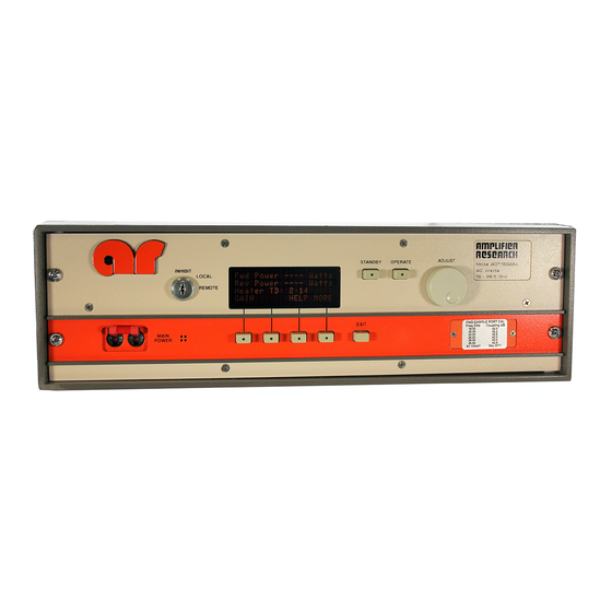
40T18G26A 3.2.8 RF Connector CAUTION: Many small RF connectors appear to be similar. Pay special attention to use only the proper mating connector for this unit. FRONT PANEL FEATURES (Refer to Figure 3-2 below). Model 40T18G26 STANDBY OPERATE 40 Watts INHIBIT 18 - 26.5 GHz LOCAL... -
Page 32: Front Panel Display And Soft-Keys
40T18G26A FRONT PANEL DISPLAY AND SOFT-KEYS The purpose of the front panel display is to permit the operator to access extensive information about the condition and operation of the TWTA. To accomplish this, a number of informational screens are programmed. It is important for the operator to be able to select the screen with the required information. Screen selection is accomplished by pressing an appropriate soft-key or by pressing the EXIT key. -
Page 33: Catalog Of Status Codes
40T18G26A Menu screens—The screens at the highest level are called menu screens. There are four menu screens. At power on, the MENU 1 screen is displayed. Each of the menu screens has the soft-key S4 labeled MORE. The MORE key (S4) causes the next menu screen to appear. From MENU 4, MORE causes MENU 1 to reappear. -
Page 34: Catalog Of Fault Codes Returned By Rdflt Command
40T18G26A To activate Sleep Mode locally: Press the MORE soft key to get to MENU 2. At MENU 2 press the SETUP soft key to get to SETUP 1. At SETUP 1 press SET to activate Sleep Mode (turn heater and fan off). The system will ask are you sure? Press SET again. -
Page 35: Catalog Of System State Codes
40T18G26A Event Screen—From MENU 4, S2 (labeled EVENT) provides a display of events logged by the control system. These events include AC power-up, heater warm-up, change from standby to operate, faults, and resets. The events are stored in a first-in-first-out (FIFO) software buffer that has room for 100 events; as new events are logged, the older ones are discarded. -
Page 36: Rear Panel Features
40T18G26A REAR PANEL FEATURES S ee Figure 3-4 below. Figure 3-4. TWTA Rear Panel Table 3-2. TWTA Rear Panel Features Item Title Function AC POWER IN AC power input connector: IEC-320 connector IEEE-488 Remote control connector: 24-pin hermaphrodite Connector to remote temperature switch protecting the isolator load: EXTERNAL INTERLOCK D-sub 15-pin female —... -
Page 37: Emergency Bypass Operation
40T18G26A Push S4 (MORE) three times to go to MENU 4. Verify that the heater voltage and current are near their nominal levels. The values of these parameters at the time the TWTA left the factory are logged on the test data sheet. - Page 38 40T18G26A Table 3-3. Catalog of IEEE-488 Commands Command Function Units Response format Returns status code of processing of previous command RDSTAT STATUS=[ ] (see Table 4) RDFLT Returns system fault code (see Table 5) flt=[ ] OPERATE; Emulates OPERATE push-button STANDBY;...
- Page 39 40T18G26A Command Function Units Response format RDPOHIW Returns over forward power warning setpoint (W) watts Pohi=[ ]W SPOHIW Sets over forward power warning setpoint (W) watts RDPOLOW Returns under forward power warning setpoint (W) watts Polo=[ ]W SPOLOW Sets under forward power warning setpoint (W) watts RDPRHID Returns over reverse power warning setpoint (dB)
-
Page 40: Model 40T18G26A Twta Troubleshooting Guide
40T18G26A Table 3-5. Catalog of Fault Codes (The RDFLT command causes the TWTA to return a string in the form flt=[code], where [code] is an ASCII number whose meaning is given below) Fault Code Meaning No fault System Fault Fil not ready Low Line Cathode overvoltage Body overcurrent... - Page 41 40T18G26A Table 3-6. Catalog of System State Codes (The RDLOGIC command causes the TWTA to send a string containing an operational state code consisting of 4 ASCII characters representing hex digits. The response is in the form Sys:[w][x][y][z][eol] where the hex values of [w],[x],[y] and [z]are formed as shown below) z bit Meaning...
- Page 42 40T18G26A Table 3-8. *STB?; Response Codes (The command *STB?; causes the TWTA to send a string containing an operational state code consisting of 2 ASCII characters representing hex digits. The response is in the form STATUS:[x][y][eol] where the hex values of [x] and [y] are formed as shown below) y bit Meaning 0 (LSB)
-
Page 43: Twta General Considerations
Cooling during Operate Mode: AR TWTAs have their air outlets and inlets on the rear panels. It is important to prevent the heated air, which is expelled from the TWTA’s air outlets, from being recycled into the air inlets. - Page 44 40T18G26A accumulates and results in a significant indication in a broadband measurement device – such as a power meter or field probe. The error produced by this indication is not significant when operating near rated TWTA power levels, but may cause difficulty when trying to operate high power TWTAs at low output power levels.
-
Page 45: Maintenance
4. MAINTENANCE The TWTA does not require routine scheduled maintenance. The unit’s only moving parts are switches, relays, and the blower. Preventive maintenance is recommended in section 4.3. It is recommended that, whenever possible, the TWTA should be returned to the factory for repair. However, since limited logic schematics and partial parts information are supplied in this manual (Section 5), some user service organizations may choose to perform their own corrective maintenance. -
Page 46: Troubleshooting
40T18G26A Disconnect power, RF, and any other interface connectors. On the rear of the unit, remove any screws used to connect brackets to the amplifier. On the front of the unit, remove the four screws holding the front panel onto the cabinet. Carefully slide the amplifier out of the front of the cabinet. Remove the 12 screws that secure the lower cover and the 12 screws that secure the upper cover. -
Page 47: Non-Repairable Modules
40T18G26A NON-REPAIRABLE MODULES The High-Voltage Diode/Capacitor Assembly (A23707-002), the High-Voltage Filter Assembly (A21457- 064), and the Heater Supply (A25963-000) are encapsulated modules and are not repairable. Contact an authorized service representative if replacement modules are needed. Rev C... - Page 48 40T18G26A Rev C...
-
Page 49: Technical Documentation
5. TECHNICAL DOCUMENTATION The purpose of this technical documentation section is to provide a guide to the TWTA for technician-level servicing. It is intended for use by qualified technical personnel who must troubleshoot and repair the TWTA in the field. Such repairs are typically limited to replacement of modules or major components. For this reason, only documentation pertaining to the highest levels of the system and to system control logic is included. -
Page 50: Top Level Build Tree
40T18G26A TOP LEVEL BUILD TREE A28050-342 HPA 40 W 18-26.5 GHZ (AR) W/TELEDYNE TUBE A22826-093 HV POWER SUPPLY FOR TWT 6193A4/D4 1A1A1 A23709-000 HEAT SINK/MOTHER BOARD ASSY 1A1A2 A23687-001 LOW VOLTAGE POWER SUPPLY MODULE 1A1A3 A16485-000 HPA LOGIC AND CONTROL MODULE... -
Page 51: Schematics
40T18G26A SCHEMATICS 10-16485-000 HPA Logic and Control (A16485-000) 10-24830-000 Emergency Bypass Board (A24830-001) 10-25444-000 HPA Interface (A25444-000) 10-28050-000 HPA 40T Series (A28050-342) Rev C... - Page 52 40T18G26A Rev C...
-
Page 53: Parts Lists
Power supply for TWT 6193 A24830-001 Emergency bypass board (for reflected foldback) A25444-000 HPA interface A28050-342 HPA 40W 18-26.5 GHz w/ Teledyne tube (AR) A28051-042 Microwave power assembly, K-band, 40 watt Teledyne tube A28052-000 Wiring kit for 40T series K/Ka TWTA Rev C... -
Page 54: Parts List, Hpa Logic And Control Module, A16485-000
40T18G26A 5.3.1 Parts List, HPA Logic and Control Module, A16485-000 REF DESIG. ETM P/N DESCRIPTION QUANTITY B16485-000 HPA LOGIC AND CONTROL BOARD C16333-000 CAP,33MF,25V,AERL,(NICHICON UVX1E330M) CAP,1000PF,200VDC,10%,CER,1% C2, C5, C15, C58 C31028-000 FAILURE,(KEMET CKR05 SERIES W/"V" OPTION) C3, C9, C10, C13, C14, C17, CAP,0.01MF,200VDC,10%,CER,1% FAILURE,(KEMET C19, C21, C22, C27, C28, C31032-000... - Page 55 40T18G26A REF DESIG. ETM P/N DESCRIPTION QUANTITY R47, R48 R22200-000 RES,20K,1/2W,1%,MF,100PPM,(DALE RN55D) R79, R80 R22470-000 RES,47K,1/2W,1%,MF,100PPM,(DALE RN55D) R42, R60, R61, R89 R23100-000 RES,100K,1/2W,1%,MF,100PPM,(DALE RN55D) R33, R55 R23698-000 RES,698K,1/2W,1%,MF,100PPM,(DALE RN55D) R23750-000 RES,750K,1/2W,1%,MF,100PPM,(DALE RN55D) R23845-000 RES,845K,1/2W,1%,MF,100PPM,(DALE RN55D) R23953-000 RES,953K,1/2W,1%,MF,100PPM,(DALE RN55D) TRIMPOT,10K,1/2W,10%,CERMET,20T,SIDE R12, R15 R32020-000 ADJ,(BECKMAN 67X) U4, U5, U6...
-
Page 56: Parts List, Hv Power Supply For Twt 6193A4/D4 A22826-093
40T18G26A 5.3.2 Parts List, HV Power Supply for TWT 6193A4/D4 A22826-093 REF DESIG. ETM P/N DESCRIPTION QUANTITY A10007-000 ANODE MODULE ASSY A10017-064 PWM BD FOR TWT TH3864C A16485-000 HPA LOGIC AND CONTROL MODULE A21457-064 HV FILTER FOR MM WAVE P/S A21458-007 HV SPURIOUS REDUCTION FILTER A23683-100... -
Page 57: Parts List, Emergency Bypass Board, A24830-001
40T18G26A 5.3.3 Parts List, Emergency Bypass Board, A24830-001 REF DESIG. ETM P/N DESCRIPTION QUANTITY B24830-000 EMERGENCY BYPASS BOARD CAP,0.1MF,100V,20%,MON,(KEMET C3-C5 C04105-000 C331C104M1R5CA) C30010-000 CAP,10MF,35V,TANT,RADIAL,(NEMCO TB10-35K1) CAP,1000PF,200VDC,10%,CER,1% C31028-000 FAILURE,(KEMET CKR05 SERIES W/"V" OPTION) CAP,0.01MF,200VDC,10%,CER,1% FAILURE,(KEMET C31032-000 CKR06 SERIES W/"V" OPTION) CAP,1MF,50VDC,10%,CER,1% FAILURE,(KEMET C31040-000 CKR06 SERIES W/"V"... -
Page 58: Parts List, Hpa Interface Board (Plastic), A25444-000
40T18G26A 5.3.4 Parts List, HPA Interface Board (Plastic), A25444-000 REF DESIG. ETM P/N DESCRIPTION QUANTITY B25444-000 HPA INTERFACE BOARD CAP,0.01MF,100V,CER,10%,RADIAL,(AVX C161 C03105-000 SR201C103KAA) C171 C04223-000 CAP,0.22MF,35V,TANT,RADIAL, [JAMCO 33507] C20, C32, C100 C05153-000 CAP,1.5MF,35V,TANT,RADIAL,(JAMECO TM1.5/35) CAP,2.2MF,35V,10%,SOLID SEALED C129, C163 C05223-000 TANT,RADIAL,(SPRAGUE 199D225X9035BA1) CAP,10MF,25V,20%,SOLID TANT,RADIAL,(AVX C80, C81, C164 C06103-000... - Page 59 40T18G26A REF DESIG. ETM P/N DESCRIPTION QUANTITY TEST JACK,BLACK,VERTICAL,(EF JOHNSON 105- J16210-000 0853-001) TEST JACK,BROWN,VERTICAL,(EF JOHNSON 105- J16211-000 0858-001) TEST JACK,RED,VERTICAL,(EF JOHNSON 105- J16212-000 0852-001) TEST JACK,ORANGE,VERTICAL,(EF JOHNSON 105- J16213-000 0856-001) TEST JACK,YELLOW,VERTICAL,(EF JOHNSON 105- J16214-000 0857-001) TEST JACK,GREEN,VERTICAL,(EF JOHNSON 105- J16215-000 0854-001) TEST JACK,BLUE,VERTICAL,(EF JOHNSON 105-...
- Page 60 40T18G26A REF DESIG. ETM P/N DESCRIPTION QUANTITY IC,INSTRUMENTATION AMP,(ANALOG DEVICES U00524-000 AD524A) (SSD) IC,DUAL 16 BIT DIGITAL TO ANALOG U00725-000 CONVERTER,(BURR-BROWN DAC-725) (SSD) IC,ADJUSTABLE VOLTAGE REGULATOR,15W,1.5A, U03171-000 TO-220,(NAT LM317T) U9, U10, U18 U04090-000 IC,4CH ANALOG MULTIPLEXER,(DATEL MXD-409) IC,8 COMMON CATHODE CLAMPIMG DIODES,9 PIN DP2, DP4, DP5, DP8, DP9 U08010-000 SIP,(ROHM DAN801)
- Page 61 40T18G26A REF DESIG. ETM P/N DESCRIPTION QUANTITY IC,10K FEED-THROUGH RES NETWORK,16 PIN RP1-RP5 U32103-000 DIP,(A/B 316B103) REGULATOR,OIL,5V,100MA,TO-92,[MOTOROLA U40008-000 MC78L05ABP] FLIP-FLOP,OCTAL D-TYPE LATCH WITH U40012-000 RESET,[NATIONAL MM74HC273N] Rev C...
-
Page 62: Parts List, Hpa 40W 18-26.5 Ghz (Ar) W/Teledyne, A28050-342
40T18G26A 5.3.5 Parts List, HPA 40W 18-26.5 GHZ (AR) w/Teledyne, A28050- REF DESIG. ETM P/N DESCRIPTION QUANTITY A22826-093 HV POWER SUPPLY FOR TWT 6193A4/D4 A23692-000 INSULATED FAN DRIVER A24830-001 EMERGENCY BYPASS BOARD A25444-000 HPA INTERFACE BOARD (PLASTIC FIBERS) A27742-000 LOW PROFILE CABINET ASSY, K AND KA-BAND... -
Page 63: Parts List, Microwave Power Assy, K Band, 40, A28051-042
40T18G26A 5.3.6 Parts List, Microwave Power Assy, K Band, 40, A28051-042 REF DESIG. ETM P/N DESCRIPTION QUANTITY E00969-000 TWT, 18 - 28 GHZ, 50 WATTS [TELEDYNE MEC-5493] E01357-000 18-26.5 GHZ SSPA, 20DBM, 24DB GAIN,(NO ATTEN.),[CPI CMA180265AXX] E01424-000 WR-42 TO COAX ADAPTOR(TYPE K), [QUINSTAR QWA-4229-CS] E01461-000 EQUALIZER, FIXED GAIN, 18-26.5 GHZ, M/F... -
Page 64: Parts List, Wiring Kit, 40W K/Ka Band, A28052-000
40T18G26A 5.3.7 Parts List, Wiring Kit, 40W K/KA Band, A28052-000 REF DESIG. ETM P/N DESCRIPTION QUANTITY P.S.,85-264VAC,47-440HZ TO 5VDC & E00765-000 3.0A,(KEPCO FAW 5-3K/CA 24) AC FILTER,IEC INPUT,250V,7A,(FILTER E00850-000 CONCEPT LF7C) FAN, 11000 RPM, 400HZ, MODEL 1284DH, E01120-000 [AMETEK 010182 MODIFIED PER DRAWING] RIBBON CABLE, 28 AWG, D-SUB 37 PIN E30147-020 FEMALE TO D-SUB 37 PIN FEMALE,[DICAR... - Page 65 40T18G26A REF DESIG. ETM P/N DESCRIPTION QUANTITY D-SUB,37 PIN,MALE,CRIMP,5A,20 AWG (ITT J31011-000 CANNON DCU-37P) CONN,D-SUB,15 PIN,FEMALE,RIBBON P7, P8 J31012-000 CABLE,W/STRAIN RELIEF, PLASTIC, [AMPHENOL 841-17-DAFR-B15S] SPRING LATCH KIT,D-SUB,(AMPHENOL 17- J31014-000 529) N22925-000 MODIFIED KNOB,1/4 SHAFT N24841-000 PANEL SWITCH SPACER SWITCH,PUSHBUTTON,SPDT,SAFETY DOOR S2, S3 S25002-000 INTERLOCK,DEFEATABLE,(MICRO SWITCH...
-
Page 66: Recommended Spare Parts
40T18G26A RECOMMENDED SPARE PARTS A10007-000 Anode module assembly A21457-064 High voltage filter assembly A23684-093 Grid modulator for TWT 3684C A23687-001 Auxiliary power supply module (low voltage power supply). A23707-002 High voltage diode/cap assembly A25963-000 Heater power supply module Y10057-000 Spinnaker DC blower (Comair Rotron model SPD24B1, part no. 032183) Rev C... -
Page 67: Sample Program For Ieee-488 Communication
40T18G26A SAMPLE PROGRAM FOR IEEE-488 COMMUNICATION 1000 ! *********************************************** 1010 IEEE-488 COMMUNICATIONS SOFTWARE 1030 7/24/92 AARON D. McCLURE 1040 ! *********************************************** 1041 DIM F$[80] 1042 DIM A$[80] 1050 CLEAR SCREEN 1060 INPUT "INPUT COMMAND TO SEND TO POWER SUPPLY. EXIT TO QUIT.",A$ 1070 IF A$="EXIT"... - Page 68 40T18G26A Rev C...
- Page 69 These modules are not field- repairable and should never be opened outside of AR’s Microelectronics Lab. The modules in these product lines have a security label on two sides of the modules between the housing and lid/cover. If the security label is removed and or cut, the warranty of the module will be voided.
Need help?
Do you have a question about the 40T18G26A Series and is the answer not in the manual?
Questions and answers