Table of Contents
Advertisement
Quick Links
Advertisement
Table of Contents

Subscribe to Our Youtube Channel
Related Manuals for IFM LI513 Series


Summary of Contents for IFM LI513 Series
- Page 1 Operating instructions Binary level sensor LI513x...
-
Page 2: Table Of Contents
Contents 1 Preliminary note ���������������������������������������������������������������������������������������������������3 1�1 Symbols used ������������������������������������������������������������������������������������������������3 2 Safety instructions �����������������������������������������������������������������������������������������������4 3 Items supplied������������������������������������������������������������������������������������������������������5 4 Functions and features ����������������������������������������������������������������������������������������5 4�1 Application area ���������������������������������������������������������������������������������������������5 4�2 Restriction of the application area �����������������������������������������������������������������5 5 Function ���������������������������������������������������������������������������������������������������������������6 5�1 Measuring principle level �������������������������������������������������������������������������������6 5�2 Measuring principle temperature �������������������������������������������������������������������6 5�3 Features of the unit ����������������������������������������������������������������������������������������7 5�3�1 IO-Link ��������������������������������������������������������������������������������������������������7... -
Page 3: Preliminary Note
10�2 Operating and diagnostic messages via IO-Link ��������������������������������������19 10�3 Operating indication by LEDs ��������������������������������������������������������������������19 10�4 Output response in different operating states ��������������������������������������������20 11 Technical data and scale drawing ��������������������������������������������������������������������20 12 Maintenance / Transport ����������������������������������������������������������������������������������20 13 Factory setting �������������������������������������������������������������������������������������������������21 1 Preliminary note 1.1 Symbols used ►... -
Page 4: Safety Instructions
2 Safety instructions • The device described is a subcomponent for integration into a system� - The system architect is responsible for the safety of the system� - The system architect undertakes to perform a risk assessment and to create documentation in accordance with legal and normative requirements to be provided to the operator and user of the system�... -
Page 5: Items Supplied
• Stainless steel tube clip (for fixing the installation height) In addition, the following is necessary for installation and operation: • Mounting material (→ Accessories) Only use accessories from ifm electronic gmbh! The optimum function is not ensured when using components from other manufacturers�... -
Page 6: Function
5 Function 5.1 Measuring principle level The unit operates on the capacitive measuring principle� In direct contact with the medium the unit detects whether the requested level (point level) has been reached� The relative permittivity (before: dielectric constant) of a medium is important for its detection�... -
Page 7: 5�3 Features Of The Unit
The IODDs necessary for the configuration of the unit, detailed information about process data structure, diagnostic information, parameter addresses and the necessary information about the required IO-Link hardware and software can be found at www�ifm�com� 5.4 Application examples 1: Overflow protection in a supply tank for coolant emulsion�... -
Page 8: Installation
6 Installation 6.1 Installation location / environment • Vertical installation from the top is preferred� • The following minimum distances must be adhered to: Distance tank bottom - end of the probe 10 mm Distance metal tank wall - probe 20 mm In case of plastic tanks: If possible, install the unit in the middle of the tank to prevent capacitive interference by... -
Page 9: 6�3 Set The Installation Depth
6.3 Set the installation depth The unit switches when the level reaches the active zone (A). The exact position (response level) depends on the following factors: • characteristics of the medium • installation conditions • adjustment of the unit (→ 9) G = point level L1 = installation depth H = tank height... -
Page 10: Electrical Connection
7 Electrical connection The unit must be connected by a qualified electrician� The national and international regulations for the installation of electrical equipment must be adhered to� Voltage supply according to EN 50178, SELV, PELV� For marine applications (if approval available for the device), additional surge protection is required�... -
Page 11: Operating And Display Elements
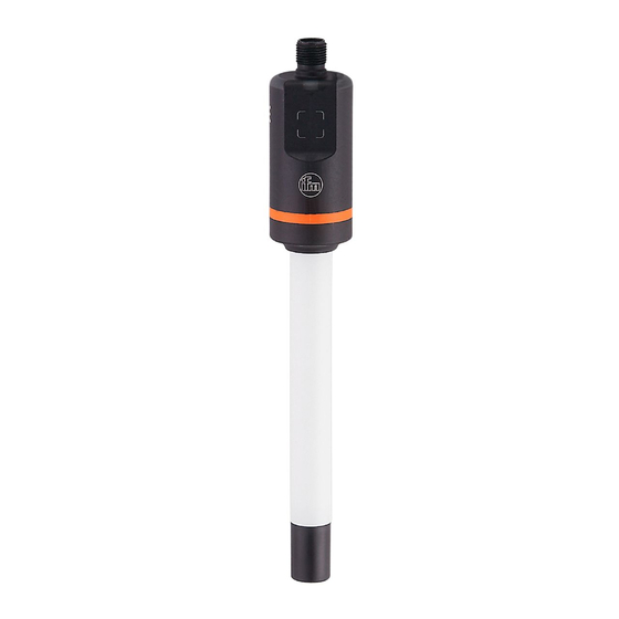
8 Operating and display elements On delivery, the two yellow LEDs (LED1 and LED2) indicate the switching status of output OUT1� This can be configured via IO-Link (→ 9.2.4)� Fig� 1: view of the unit Fig� 2: top view 1: LED1 (yellow) = switching status OUT1 1: inductive teach button 2: LED2 (yellow) = switching status OUT1 (OUT2) -
Page 12: 9�1 Parameter Setting Via The Teach Button
► Make sure that there will be no malfunctions / dangerous operation in your plant� 9.1 Parameter setting via the teach button The teach button can be used to unlock the unit in a first step (→ 9.1.1) and then to adjust the unit sensitivity� The unit sensitivity is adjusted by carrying out an empty adjustment and / or a full adjustment (→... -
Page 13: 9�1�2 Set For Empty Tank Condition
9.1.2 Set for empty tank condition By performing the empty adjustment, the unit is adjusted to the empty tank and the installation conditions (e.g. the distance to the tank wall / structures in the tank). Previous adjustment operations are deleted� By performing the empty adjustment, the unit is adjusted to maximum sensitivity which is particularly suitable for media with a low dielectric constant (e.g. -
Page 14: 9�1�3 Set For Full Tank Condition
9.1.3 Set for full tank condition In case of aqueous media, in particular those where deposits or soiling are to be expected, the empty adjustment is not necessary and a full adjustment can be carried out immediately� Where an empty adjustment has been carried out for aqueous media, it must be followed by a full adjustment to achieve a perfect adjustment of the unit sensitivity to the medium�... -
Page 15: 9�2 Parameter Setting Via Io-Link
9.2 Parameter setting via IO-Link A PC with USB IO-Link master (→ 9.2.1) or a programmed memory plug (→ 9.2.2) or a configured IO-Link environment (→ 9.2.3) is required to set the parameters� 9.2.1 Parameter setting via PC and IO-Link master ►... -
Page 16: 9�2�4 Adjustable Parameters And System Commands
9.2.4 Adjustable parameters and system commands Parameter uni�T Selection of the temperature unit: [°C] = temperature is displayed in °C (degrees Celsius) [°F] = temperature is displayed in °F (degrees Fahrenheit) Set output logic for the switching outputs: [PnP] = positive switching [nPn] = negative switching SEL2 Allocation of switching output OUT2 to the process value:... - Page 17 SP2 (FH2) - TEMP Switch point 2 or upper temperature limit for window function ([SEL2]=[TEMP]). [SP2 (FH2)] must be greater than [rP2 (FL2)]. If [SP2 (FH2)] is set to a value below [rP2 (FL2)], this is rejected by the device software� rP2 (FL2) - TEMP Switch point 2 or lower temperature limit for window function ([SEL2]=[TEMP]).
-
Page 18: 9�2�5 Example Parameter Setting Via Io-Link
The indication automatically disappears after 1 minute� Flash Off Visual indication (double flash) for localisation OFF. For further information, please refer to the IODD description (→ www.ifm.com) or to the context-specific parameter descriptions of the used parameter setting software� 9.2.5 Example parameter setting via IO-Link ►... -
Page 19: Operation
► Check whether the unit operates reliably� 10.2 Operating and diagnostic messages via IO-Link IODD and IODD descriptive text as a pdf file at: → www.ifm.com 10.3 Operating indication by LEDs The following indications refer to the factory settings� In this state OUT1 = Hno and OUT2 = Hnc�... -
Page 20: 10�4 Output Response In Different Operating States
[FOU1] acc� to setting [FOU2] 11 Technical data and scale drawing Technical data sheet and scale drawing at: → www.ifm.com 12 Maintenance / Transport ► Clean the sensor tip at regular intervals to avoid contamination over time or formation of deposits�... -
Page 21: Factory Setting
FOU2 Lo.T Hi.T Percentage values refer to the process value. 0% corresponds to the measured value in air (not predamped), 100 % corresponds to the measured value in water (tap water in a grounded metal tank). More information at www�ifm�com...
Need help?
Do you have a question about the LI513 Series and is the answer not in the manual?
Questions and answers