Table of Contents
Advertisement
Quick Links
Advertisement
Table of Contents
Troubleshooting

Related Manuals for IFM LW2120


Summary of Contents for IFM LW2120
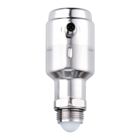
- Page 1 Operating instructions Electronic level sensor LW2120...
-
Page 2: Table Of Contents
LW2120 Electronic level sensor Contents Preliminary note ............. - Page 3 Electronic level sensor LW2120 10 Factory setting ............. . 36 11 Appendix.
-
Page 4: Preliminary Note
LW2120 Electronic level sensor 1 Preliminary note You will find instructions, technical data, approvals and further information using the QR code on the unit / packaging or at www.ifm.com. 1.1 Symbols used Requirement Instructions Reaction, result [...] Designation of keys, buttons or indications... -
Page 5: Safety Instructions
Electronic level sensor LW2120 2 Safety instructions • Read this document before setting up the product and keep it during the entire service life. • The product must be suitable for the corresponding applications and environmental conditions without any restrictions. •... -
Page 6: Intended Use
In addition, the following is necessary for installation and operation: • Mounting material (Ò Accessories) Only use accessories from ifm electronic gmbh! The optimum function is not ensured when using components from other manufacturers. Available accessories: www.ifm.com. 3.1 Application area With its top-down installation, the non-contacting radar technology is ideally suited for level monitoring and is virtually maintenance-free. -
Page 7: Restriction Of The Application Area
Electronic level sensor LW2120 Open application: Level monitoring in open applications independent of surface and weather conditions. 3.2 Restriction of the application area • The device is not approved for use in potentially explosive atmospheres. • The unit is not suitable for all bulk materials (e.g. dry building materials) due to their very low dielectric constant. -
Page 8: Function
LW2120 Electronic level sensor 4 Function 4.1 Measuring principle The measuring principle of the unit is Frequency Modulated Continuous Wave (FMCW). The unit continuously emits electromagnetic waves in the GHz range with a constantly varying frequency towards the medium surface. Since the transmitter continuously changes the frequency of the transmitted signal, there will be a difference in frequency between the transmitted and the reflected signals (Ò... -
Page 9: Foam And Turbulence
Electronic level sensor LW2120 4.1.2 Foam and turbulence Foaming liquids or turbulence may cause weak and varying echo amplitudes. Surface turbulence is not normally a problem unless it is excessive. Measurement in foamy applications depends largely on the foam properties. If the foam is light and airy, the actual level is measured. -
Page 10: Switching Function
LW2120 Electronic level sensor • If [ASP2] is set lower than [AEP2], a rising curve results; if [ASP2] is set higher than [AEP2], a dropping curve results (Ò Fig. Analogue output). Minimum distance between [ASP2] and [AEP2] = 20 % of the active zone... -
Page 11: Defined State In The Event Of A Fault (Alert Mode)
Electronic level sensor LW2120 Fig. 3: Single-point mode Fig. 4: Two-point mode level time hysteresis Window function: u [SSC1 Config. Mode] must be set to [Window]. The width of the window can be set by means of the difference between [SSC1 Param. SP1] and [SSC1 Param. -
Page 12: Simulation Function
LW2120 Electronic level sensor unit continues to work in normal operation. If, however, it is not received again with sufficient strength within the delay time, the unit passes into the alert mode and output OUT2 changes into the defined state. -
Page 13: Mounting
Electronic level sensor LW2120 5 Mounting CAUTION With high process temperatures, parts of the unit may get hot. w Risk of burns u Do not touch the unit. u Protect the housing against contact with flammable substances and unintentional contact. u Allow the unit and process adapter to cool down before maintenance. -
Page 14: Inclination
LW2120 Electronic level sensor 5.2 Inclination u Mount the unit vertically (90°) to ensure a good echo from the medium surface. u Maximum inclination (1): 3° (Fig. Inclination). 90° Fig. 7: Inclination 5.3 Polarisation and orientation The unit emits electromagnetic waves for level detection. The polarisation is the direction of the electrical component of these electromagnetic waves. -
Page 15: Installing The Mounting Bracket
Electronic level sensor LW2120 5.5 Installing the mounting bracket 90° Fig. 10: Horizontal installation of the mounting bracket 90° Fig. 11: Vertical installation of the mounting bracket u Align and install the mounting bracket on a flat surface. u To be able to change the device mounting area of the bracket, loosen the fixing screws of the bracket. -
Page 16: Mount The Antenna Extension
LW2120 Electronic level sensor u Before installing, carefully remove the protective cap. u Be careful not to scratch or otherwise damage the antenna. 5.6.2 Mount the antenna extension u Spread an adequate amount of lubricating paste on the unit thread. The lubricating paste must be approved for the application and compatible with the elastomers used. -
Page 17: Electrical Connection
Electronic level sensor LW2120 5.7 Electrical connection The unit must be connected by a qualified electrician. The national and international regulations for the installation of electrical equipment must be adhered to. Supply voltage SELV, PELV according to the technical data sheet. -
Page 18: Parameter Setting
LW2120 Electronic level sensor 6 Parameter setting Changing parameters during operation can influence the function of the plant. u Make sure that there will be no malfunctions or dangerous operation in your plant. The device parameters are set via the IO-Link interface. For this, an IO-Link master, IO-Link parameter setting software (Ò... -
Page 19: Parameter Setting Via Bluetooth Adapter
Electronic level sensor LW2120 Fig. 14: Connection example with PLC u Read the unit using a suitable IO-Link software (Ò Observe the operating instructions of the respective software). u Set the parameters. Before parameter setting, familiarise yourself with all the parameters. - Page 20 LW2120 Electronic level sensor Parameter Options Explanation Access Negative level [Equal to zero] = negative levels (below the If the tank offset is > 0, the level value can be zero point) are not displayed. negative. This parameter defines whether nega- tive levels are displayed or whether they should [Permitted] = negative levels are displayed.
- Page 21 Electronic level sensor LW2120 Parameter Options Explanation Access SSC2 Param. SP1 Setting range: 0.005...15 m Set point 1 for SSC2 (switching channel 2). Only available if SSC2 is not deactivated. Set point 1 must be smaller than or equal to the set tank height [Reference height].
- Page 22 LW2120 Electronic level sensor Reference height: device reference point (lower edge/sealing edge of the process connec- tion) reference height (measuring range) zero point (tank bottom or lower end of the measuring range) Fig. 15: Reference height The reference height is used to define the zero point and thus the reference point for the level measurement.
- Page 23 Electronic level sensor LW2120 • False echoes within the tank offset which affect the measurement and lead to measurement errors are detected and, where necessary, communicated after the delay time has elapsed (see parameter [Alert mode delay time]). • Take into account agitators and objects in the lower tank section that could cause false echoes.
-
Page 24: System Commands
LW2120 Electronic level sensor 6.5 System commands Start simulation Starts the simulation mode. The level set under the parameter [S.Lvl] is simulated. Stop simulation Stops the simulation. Reset to factory settings. Restore factory settings (all parameters). On delivery the unit is not operational. - Page 25 Electronic level sensor LW2120 u Configure analogue output: Use [ASP2] and [AEP2]. u Configure switching output OUT1: Use [SSC1...] parameter.
-
Page 26: Operation
LW2120 Electronic level sensor 7 Operation 7.1 Function check After power-on and the required parameter setting the unit is in the operating mode. It carries out its measurement and evaluation functions and generates output signals according to the set parameters. u Check whether the unit operates correctly. - Page 27 • Verify operating voltage is between 18-30 V. Maintenance required – Cleaning. Product build-up on the antenna. • Clean the antenna. For further information, please refer to the IODD description (www.ifm.com) or to the context-specific parameter descriptions of the used parameter setting software.
-
Page 28: Troubleshooting
LW2120 Electronic level sensor 8 Troubleshooting 8.1 Troubleshooting incorrect level readings 8.1.1 Level too high / too low level time actual level measured level Possible cause: • Incorrect tank geometry configuration. Recommended actions: • Verify the tank geometry parameters are configured correctly, especially the reference height. -
Page 29: Measured Value Drops When Level Close To Antenna
Electronic level sensor LW2120 Possible cause: • Disturbing object in the tank. 15° Recommended actions: • Analyse the echo peaks and check the detection threshold. • If possible, remove the disturbing object or change the device position. • Rotate the unit in steps of about 15 degrees. -
Page 30: Measured Value Fluctuates
LW2120 Electronic level sensor level time actual level measured level Possible cause: • The level is within the upper blind zone and a false echo is interpreted as the level. Recommended actions: • Check the setting of the upper blind zone. -
Page 31: Measured Value Is Occasionally Unstable
Electronic level sensor LW2120 8.1.5 Measured value is occasionally unstable level time actual level measured level Possible cause: • The level is close to a suppressed false echo. Recommended actions: • If possible, remove the disturbing object or change the device position. -
Page 32: Measured Value Correct At 0% (4 Ma) But Incorrect At 100% (20 Ma)
LW2120 Electronic level sensor 8.1.7 Measured value correct at 0% (4 mA) but incorrect at 100% (20 mA) level time actual level measured level Possible cause: • Analogue end point (parameter [AEP2]) is not set correctly. Recommended actions: • Correct parameter [AEP2]. 8.1.8 Incorrect measured value when level is above 50%... -
Page 33: Level Measurement Is Lost In An Empty Tank
Electronic level sensor LW2120 level time actual level measured level Possible cause: • A strong tank bottom echo is interpreted as the level. Recommended actions: • Verify the reference height is configured correctly. • With very low dielectric media: Reduce the reference height and configure a tank offset. -
Page 34: Alert Mode When Level Close To Tank Bottom
LW2120 Electronic level sensor 8.1.11 Alert mode when level close to tank bottom When the level is near the sloped tank bottom, the device enters the alert mode. level time actual level measured level Fig. 18: Possible cause: • Radar signal is scattered to the side by the sloped tank bottom. -
Page 35: Maintenance, Repair And Disposal
Electronic level sensor LW2120 9 Maintenance, repair and disposal The unit can be unscrewed from the adapter for cleaning. u Check the unit and the mounting adapter at regular intervals and tighten again, if necessary. u Only use suitable tools with plastic wrench flats for wetted surfaces. - Page 36 LW2120 Electronic level sensor 10 Factory setting Parameter Factory setting User setting Access Application Specific Tag Function Tag Location Tag Reference height Initial value tank offset 0 (m) Upper blind zone 0 (m) out1/out2 SSC1 / I (4…20 mA) dS1/dS2 0 (s) dr1/dr2 0 (s) SSCx* Param.
- Page 37 Electronic level sensor LW2120 11 Appendix 11.1 Approvals and certificates The EU declaration of conformity, approvals and country-specific certificates are available at: www.ifm.com Approval-related notes: Ò Packing slip...
Need help?
Do you have a question about the LW2120 and is the answer not in the manual?
Questions and answers