Table of Contents
Advertisement
Quick Links
Advertisement
Table of Contents

Subscribe to Our Youtube Channel
Related Manuals for IFM LR3009


Summary of Contents for IFM LR3009
- Page 1 Operating instructions Electronic level sensor LR3009...
-
Page 2: Table Of Contents
LR3009 Electronic level sensor Contents Preliminary note ............. - Page 3 Electronic level sensor LR3009 9.7.7 Scaling the analogue signal ......... . . 29 9.7.8...
-
Page 4: Preliminary Note
LR3009 Electronic level sensor 1 Preliminary note You will find instructions, technical data, approvals and further information using the QR code on the unit / packaging or at www.ifm.com. 1.1 Symbols used Requirement Instructions Reaction, result [...] Designation of keys, buttons or indications... -
Page 5: Safety Instructions
Electronic level sensor LR3009 2 Safety instructions • The unit described is a subcomponent for integration into a system. – The system architect is responsible for the safety of the system. – The system architect undertakes to perform a risk assessment and to create documentation in accordance with legal and normative requirements to be provided to the operator and user of the system. -
Page 6: Intended Use
Plus one coaxial pipe (for operation of the device with coaxial probe) Ò Accessories. Mounting material (if necessary, a launching plate) Ò Accessories. • 3.1 Accessories Only use accessories from ifm electronic gmbh. The function is not ensured when using components from other manufacturers. The following components are available as accessories: Rods... -
Page 7: Operation With Single Probe
Electronic level sensor LR3009 Coaxial pipes with ¾“ NPT process connection Length (cm) Order number E43218 E43219 E43220 E43223 E43224 E43221 Flange plates Size / process connection Order number 73 - 90 / G¾ E43201 65 - 80 / G¾... -
Page 8: Restriction Of The Application Area
LR3009 Electronic level sensor 3.4.1 Restriction of the application area Incorrect measurements or signal loss may be caused by the following media: Highly absorbing surfaces (e.g. foam). Intensely bubbling surfaces. Media which are very inhomogeneous, separate from each other thus forming separation layers (e.g. -
Page 9: Function
The IODDs necessary for the configuration of the unit, detailed information about process data structure, diagnostic information, parameter addresses and the necessary information about the required IO-Link hardware and software can be found at www.ifm.com. 4.1 Measuring principle The device operates on the principle of guided wave radar. It measures the level using electromagnetic pulses in the nanosecond range. -
Page 10: Switching Function
LR3009 Electronic level sensor Analogue start point [ASP2] defines at which measured value the output signal is 4 mA / 0 V ([OU2] = [I] / [U]) or 20 mA / 10 V ([OU2] = [InEG] / [UnEG]). Analogue end point [AEP2] defines at which measured value the output signal is 20 mA / 10 V ([OU2] = [I] / [U]) or 4 mA / 0 V ([OU2] = [InEG] / [UnEG]). Minimum distance between [ASP2] and [AEP2] = 25 % of the active zone. -
Page 11: Offset For Indicating The Real Level In The Tank
Electronic level sensor LR3009 • Window function / normally open (Fig. Hysteresis function): [OU1] = [Fno]. • Window function / normally closed (Fig. Window function): [OU1] = [Fnc]. The width of the window can be set by means of the difference between FH1 and FL1. -
Page 12: Installation
LR3009 Electronic level sensor 5 Installation Vertical installation from the top is preferred. 5.1 Device with single probe For a safe function, the device requires a launching plate. The following minimum distances between the rod and tank walls, objects in the tank (B), tank bottom... - Page 13 Electronic level sensor LR3009 Fig. 5: Installation on a pipe Fig. 6: Installation in a boss Although the device can be installed in a boss: installation in a flat tank lid is recommended, as a boss will impede the distribution of the microwaves.
-
Page 14: Device With Coaxial Probe
LR3009 Electronic level sensor Min. diameter bypass and still pipe Upper access to the steady area Upper access to the steady area Lower access to the steady area Lower access to the steady area 5.2 Device with coaxial probe • No minimum distances to the tank wall and structures in the tank (B) are required. -
Page 15: Installation Of The Coaxial Pipe
Electronic level sensor LR3009 Substances such as screw retaining compounds may migrate into the medium. u Make sure that they are harmless. When using mechanical means of securing (e.g. tooth lock washer), protruding edges must be avoided. They may cause interference reflection. -
Page 16: Determination Of The Probe Length L When Coaxial Probes Are Used
LR3009 Electronic level sensor u Remove the fastening bracket and the centring piece (A, B). u Shorten the coaxial pipe to the requested length: L = L + 9 mm. u After shortening, at least one hole (C) for insertion of the fixing bracket has to be left. -
Page 17: Installation In Closed Metal Tanks (With Flange Plate)
Electronic level sensor LR3009 u Avoid non-flush installation. u If necessary, use seals or washers (D) to reach the required height. u For tanks with thick walls arrange for sufficiently deep recesses to ensure flush installation. 5.5.2 Installation in closed metal tanks (with flange plate) Flange plates are not supplied. -
Page 18: Installation In Open Tanks
LR3009 Electronic level sensor 5.5.3 Installation in open tanks u For installation in open tanks, use a metal fixture to install the device. It serves as a launching plate (R); minimum size: 150 x 150 mm for a square fixture, 150 mm diameter for a circular fixture: (Ò... -
Page 19: Alignment Of The Sensor Housing
Electronic level sensor LR3009 • For pipes with ¾" NPT process connection: apply a suitable sealing material (e.g. Teflon tape). u Screw the device with the coaxial pipe into the tank and tighten it. 5.7 Alignment of the sensor housing After installation, the sensor housing can be aligned. It can be rotated without restriction. Even if... -
Page 20: Electrical Connection
LR3009 Electronic level sensor 6 Electrical connection The device must be connected by a qualified electrician. The national and international regulations for the installation of electrical equipment must be adhered to. Supply voltage SELV, PELV according to the technical data sheet. -
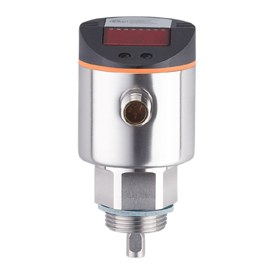
Page 21: Operating Elements And Display Elements
Electronic level sensor LR3009 7 Operating elements and display elements Mode/Enter 1 to 8: Indicator LEDs LED 1 green = indication of the level in cm. LED 2 not used. LED 3 green = indication of the level in % of the final value of the measuring range. -
Page 22: Menu
LR3009 Electronic level sensor 8 Menu 8.1 Menu structure ---- 21,0 20,5 FOU1 FOU2 ASP2 AEP2 21.0 SELd LEnG 24.0 MEdI HIGH Prob COAX 8.2 Explanation of the menu SP1/rP1 Upper / lower limit value for the level at which OUT1 switches. FH1/FL1 Upper / lower limit for the acceptable range (monitored by OUT1). - Page 23 Electronic level sensor LR3009 FOU2 Response of OUT2 in case of a fault. Delay time for the outputs to pass into the safe state. ASP2 Analogue start point for level: Measured value at which the analogue start value is provided. The analogue start value is set with parame- ter [OU2].
-
Page 24: Parameter Setting
LR3009 Electronic level sensor 9 Parameter setting The parameters can be set via the buttons on the device or the IO-Link interface. During parameter setting the device remains in the operating mode internally. It continues its monitoring functions with the existing parameters until the parameter setting has been completed. - Page 25 Electronic level sensor LR3009 w The numerical values are incremented continuously. For reducing the value: u Let the display move to the maximum setting value. Then the cycle starts again at the minimum setting value. 3: Acknowledge parameter value u Briefly press [Mode/Enter].
-
Page 26: Basic Settings (On Delivery)
LR3009 Electronic level sensor u Make sure that the device is in normal operating mode. u Press [Mode/Enter] + [Set] simultaneously for 10 s. w [Loc] is displayed. [Loc] is briefly displayed if you try to change parameter values. Unlocking: uLoc u Press [Mode/Enter] + [Set] simultaneously for 10 s. -
Page 27: Setting To The Medium
Electronic level sensor LR3009 9.3.2 Setting to the medium u Select [MEdI], press [Set] for 5 s. [MEdI] w [nonE] is displayed. u Set the requested value: • [HIGH] for water and water-based media. • [LOW] for oils and oil-based media. -
Page 28: Configuring The Display
LR3009 Electronic level sensor The setting ranges for analogue start point (ASP2) and analogue end point (AEP2) depend on the probe length (L). In general, the following applies: min. max. ASP2 1.0 (3.0) AEP2 L - 3.0 Step increment Minimum distance between [ASP2] and [AEP2] = 25 % of the active zone. The values apply if [OFS] = 0. -
Page 29: Setting The Switching Limits (Window Function)
Electronic level sensor LR3009 9.7.3 Setting the switching limits (window function) u Make sure that for [OU1] the function [Fno] or [Fnc] is set. [FH1] u Select [FH1] and set the upper limit of the acceptable range. u Select [FL1] and set the lower limit of the acceptable range. -
Page 30: Resetting All Parameters To Factory Setting
LR3009 Electronic level sensor 9.8 Resetting all parameters to factory setting u Select [rES], then press [Set] and keep it pressed until [----] is displayed. [rES] u Briefly press [Mode/Enter]. w The device reboots and then the factory settings are restored. -
Page 31: Operation
Electronic level sensor LR3009 10 Operation After power-on and expiry of the power-on delay time of approx. 0.5 s the unit is in the RUN mode (= normal operating mode). It carries out its measurement and evaluation functions and generates output signals according to the set parameters. -
Page 32: Output Response In Different Operating States
LR3009 Electronic level sensor Indication Possible cause Recommended actions [E.033] Rod or process connection soiled. Clean the rod and the process connection, then carry out a reset.* Installation conditions were not adhered to. Observe the notes in "Installation". Probe length, type of probe or sensitivity (setting to Correct the settings, then carry out a reset.*... -
Page 33: Repair, Maintenance And Disposal
Electronic level sensor LR3009 11 Repair, maintenance and disposal u After use dispose of the unit in an environmentally friendly way in accordance with the applicable national regulations. u For transport only use appropriate packaging to avoid damage of the unit. -
Page 34: Factory Setting
LR3009 Electronic level sensor 12 Factory setting Factory setting User settings SP1 / FH1 100% SP/FHmax rP1 / FL1 100% rP/FLmax FOU1 FOU2 ASP2 1.0 (3.0)* AEP2 AEP2max SELd LEnG nonE MEdI nonE Prob nonE SP/FHmax, AEP2max = LEnG value minus 3.
Need help?
Do you have a question about the LR3009 and is the answer not in the manual?
Questions and answers