Table of Contents
Advertisement
Quick Links
INSTALLATION, OPERATION AND MAINTENANCE INSTRUCTIONS
SKOTCH
WARNING
Valves and valve actuators supplied by ITT Engineered Valves, LLC are designed and
manufactured using good workmanship and materials, and they meet the applicable
industry standards. These valves are available with components of various materials, and
they should be used only in services recommended herein or by a company valve engineer.
Misapplication of the product may result in injuries or property damage. A selection of
valve components of the proper material consistent with the particular performance
requirement, is important for proper application.
Examples of the misapplication or misuse of a valve or valve actuator includes use in an
application that exceeds the pressure/temperature rating, or failure to maintain the
equipment as recommended.
Technical Manual No. IOT1000P
ITT Engineered Valves, LLC
33 C
ENTERVILLE
L
, PA 17603-2064
ANCASTER
T
: (717) 509-2200
EL
F
: (717) 509-2336
AX
www.engvalves.com
MODEL T1005, T1006, T1007 & T1008
TRIFECTA
R
OAD
OIL VALVE SYSTEMS
Effective 8/31/2018
REV LEVEL B
Advertisement
Table of Contents

Subscribe to Our Youtube Channel
Related Manuals for ITT SKOTCH TRIFECTA T1005


Summary of Contents for ITT SKOTCH TRIFECTA T1005
- Page 1 OIL VALVE SYSTEMS WARNING Valves and valve actuators supplied by ITT Engineered Valves, LLC are designed and manufactured using good workmanship and materials, and they meet the applicable industry standards. These valves are available with components of various materials, and they should be used only in services recommended herein or by a company valve engineer.
- Page 2 Record of Revisions Revision Description Date First Issue 09/10/99 Added reference information for T1007 (Fail in Last 03/23/04 Position Fire, Fail Closed Purge) Revised Model T1007 to Fail-Closed Non-FM, 08/31/18 Model T1008 as FLFC and manual. Technical Manual No. IOT1000P Effective 8/31/2018 REV LEVEL B...
-
Page 3: Table Of Contents
TABLE OF CONTENTS SECTION PAGE Description ..................Operation ..................III. Installation ..................Maintenance & Disassembly Instructions ........Leak Testing .................. Proof of Closure Switch Testing ........... VII. Miscellaneous Instructions for Special Options ......VIII. Spare Parts Ordering Information ..........Reference Information ..............DRAWINGS 03-001 Valve Assembly - Model T1000 Systems... -
Page 4: Description
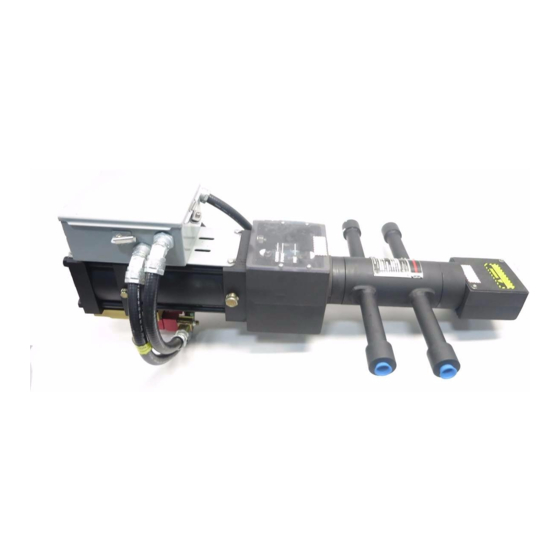
Page 4 of 22 Engineered Valves, LLC DESCRIPTION The Model T1005, T1006, T1007 and T1008 Oil Valves are an integral valve system with all components housed within a single valve body. It is typically used on all oil-fired burners and igniters where steam or air atomization is required. The Skotch Trifecta's unique two-stem three-seat design enables it to perform all key functions, including fuel sequencing, atomization and purging of downstream piping by providing three distinct valve positions. -
Page 5: Operation
Page 5 of 22 Engineered Valves, LLC OPERATION Refer to Purchase Order Specification or solenoid valve assembly nameplate to determine proper line voltage. Operation is in accordance with reference drawings. Check specific order options and wiring diagrams (60-008 for AC voltage or 60-009 for DC voltage) for electrical terminals supplied inside the junction box. - Page 6 Page 6 of 22 Engineered Valves, LLC Operational Note: While in the Fire position there is an operational advantage in leaving the Purge solenoid energized while in Fire. In this scenario both actuator cylinders will be pressurized. Doing so will prevent the valve from traveling back to the Closed position causing a momentary loss in Purge pressure.
-
Page 7: Installation
Page 7 of 22 Engineered Valves, LLC Assemblies may include a speed control (black in color) which is located between the Fire solenoid body (red anodize) and the manifold adapter (gold anodize). This is used to slow opening time of the assembly when moving to the "Fire" position. - Page 8 Page 8 of 22 Engineered Valves, LLC Valve Installation The oil valve installation should be in accordance with standard practices for end connection selected. Valves with weld end connections are supplied with end connections of sufficient length to prevent thermal damage to valve internals. As a safety precaution, methods to thermally block the transfer of heat to the valve body should be employed during welding.
- Page 9 Page 9 of 22 Engineered Valves, LLC Pneumatic/Electrical Hook Up Electrical power and clean dry air are required to operate the T1000 oil valve system. Wiring should be in accordance with referenced drawings and all applicable codes. All wiring connections are on the main terminal board located inside the Junction Box.
-
Page 10: Maintenance & Disassembly Instructions
Page 10 of 22 Engineered Valves, LLC Start-Up When valve is placed in service, stroke the main stem and oil stem two or three times (Fire cycles) and then check for packing leaks. If leakage is present, tighten adjusting nut 1/8 turn, stroke valve several times to ensure proper setting of packing and recheck. - Page 11 Page 11 of 22 Engineered Valves, LLC Packing Inspection Both the oil valve and the atomizing packing should be inspected regularly for leakage. If any leakage is noted the packing should be adjusted until the leakage has stopped. See Section III.D for instructions. Pneumatic System Leaks The pneumatic system (fittings, solenoid, actuator, etc.) should be inspected regularly for leakage or other damage.
- Page 12 Special tools are needed to remove the valve seats. The following tools are available: ITT P/N: 44425, T1000/T2000 seat ring tool. This tool will remove all three seats (atomizing, purge and oil) from the oil valve body and is needed when servicing the atomizing side of the valve.
- Page 13 Page 13 of 22 Engineered Valves, LLC After completing Paragraph IV.B.1, unscrew Socket Head Cap Screws (Item 6) which retain End Flange (Item 2) to Body (Item 1). Remove End Flange and Body Gasket (Item 7). Be sure to thoroughly clean mating gasket surface, but do not damage it.
- Page 14 Page 14 of 22 Engineered Valves, LLC Packing Removal After removing end flanges in Paragraphs IV.B.2 and IV.B.3 above, unscrew Packing Nut (Item 3) and remove Packing (Item 4) and Packing Spring (Item 5). Actuator Disassembly The actuator should not be disassembled or repaired. Consult factory. Inspection After disassembly, inspect all sealing and bearing surfaces on valve and actuator parts for physical damage including nicks, scratches or corrosion.
- Page 15 Page 15 of 22 Engineered Valves, LLC Packing/End Flange Reassembly Place Packing Spring (Item 5) in stuffing box. Lubricate each individual packing component (Item 4) with KRYTOX lubricant from DuPont. Individually install the components into the End Flange. The assembly order is male ring first, then chevrons, then female ring.
- Page 16 Page 16 of 22 Engineered Valves, LLC Seat (Item 17). Tighten the Set Screw (Item 18) so the spring seat is secure. Remove the Limit Switch Box (Item 13). Place Oil Valve Return Spring (Item 19) into the Spring Seat (Item 17) and mount the Limit Switch Box (Item 13) using the 2 mounting Nuts (Item 29) with Lock Washers (Item 28).
- Page 17 Page 17 of 22 Engineered Valves, LLC Actuator Reinstallation Carefully place actuator onto valve. Screw yoke lock nut onto valve end flange (Item 2) hand tight. Slide valve stem up and thread stem connector onto actuator shaft. Rotate slowly until resistance is felt. Securely tighten yoke lock nut.
-
Page 18: Leak Testing
Page 18 of 22 Engineered Valves, LLC Leak Testing After assembly, the Skotch Trifecta Valve should be leak tested to verify proper operation as follows: Atomizing Seat Place the valve in the Closed position. The fuel inlet and outlet ports must be plugged so that test media cannot escape for these ports. -
Page 19: Proof Of Closure Switch Testing
Page 19 of 22 Engineered Valves, LLC Pressurize the atomizing inlet to 50 PSIG (344.7 KPa) air while monitoring the fuel outlet port for leakage. The allowable leakage rate per ANSI Class IV is 439 cc/min. If leakage is excessive, stroke the valve 10 to 20 times to allow the metal seat to wear in with the metal plug and retest the valve. - Page 20 Page 20 of 22 Engineered Valves, LLC assumes the valve actuator is on top) to edge of slot or until switch boot hits the edge of the hole. This will typically move the switch roller actuator past the tripping device. Move the switch away from the end flange (down) until it trips.
- Page 21 Page 21 of 22 Engineered Valves, LLC GO Switches Ensure the valve is in the closed position. Wire the switch to a test device. Loosen switch and push it towards the end flange (up - orientation assumes the valve actuator is on top) to top of slot of POC box. This will typically move the switch past the target device.
-
Page 22: Miscellaneous Instructions For Special Options
Phone: 717-509-2200 Fax: 800-348-9000 Please be advised that spare parts should be ordered directly from ITT Engineered Valves, as such materials are specially designed for Skotch Trifecta Valve Systems. Other replacement parts, although they may be similar in function, will void the FM rating.
Need help?
Do you have a question about the SKOTCH TRIFECTA T1005 and is the answer not in the manual?
Questions and answers