Table of Contents
Advertisement
Quick Links
Antaira Technologies
LNP-0500G-24 Series
5-Port Industrial PoE+ Unmanaged Gigabit Ethernet Switch,
w/4*10/100/1000Tx (30W/Port) + 1*10/100/1000Tx, 12~36VDC
Quick Installation Guide
Version 1.1
(January 2019)
Tel: 1-844-268-2472
Fax: 1-714-671-9944
www.antaira.com
Package Check List
The package contains the following items:
⚫
1 – Quick installation guide
⚫
1 – LNP-0500G-24(-T)
1 – Wall mounting bracket set with screws
⚫
⚫
1 – DC cable –18 AWG & DC jack 5.5 x 2.1mm
⚫
1 – RJ45 dust cover set
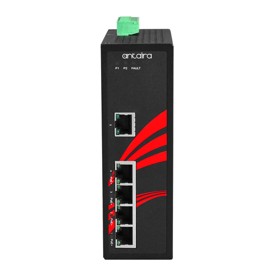
Front Panel Layout
Grounding Screw
LAN# 1~5 – LED for Link/Activity Status
1000Mbps
LAN# 1~5 – LED for Link/Activity Status
10/100Mbps
LAN# 1~4 – LED for PoE Status
Top Panel View
LNP-0500G-24 series top panel is equipped with one 6-pin
removal terminal block connector for dual DC power inputs
(12~36VDC).
6-Pin Removal Terminal Block (Power Input)
Grounding Screw
Product Overview
System Interface/Performance
All RJ45 ports support the auto MDI/MDI-X function
Embedded 4*10/100/1000Tx (PSE 30W/Port) and
1*10/100/1000Tx Fast Ethernet
Store-and-Forward switching architecture
8K MAC Address Table
19020000000035
Power Input & Connection
DC 12 to 36V redundant power, with a 6-pin removal
terminal block
It is recommended to use a UL listed industrial power supply
Operating Temperature
Standard Operating Temperature model: -10°C to 70°C
Extended Operating Temperature model: -40°C to 75°C
Case/Installation
IP30 Protection
DIN-Rail and Wall Mount Design
6-Pin Removal Terminal Block (Power Input)
LED Indicators
LED
LED for Power 1, Power 2 and Fault
Power 1
Power 2
LAN# 1~5 – 10/100/1000Tx RJ45
Fault
PoE Indicator
(Port 1~4)
LAN Port 1~5
(Upper LED)
LAN Port 1~5
(Lower LED)
Quick Installation
Ethernet Ports
RJ45 Ports (Auto MDI/MDIX)
All RJ45 ports are auto-sensing for 10Base-T, 100Base-TX, or
1000Base-T device connections. Please follow the wiring pin
assignment table below for Ethernet port installation.
Pins
Pin 1
white/green stripe
Pin 2
Pin 3
white/orange stripe
Pin 4
Pin 5
Pin 6
Pin 7
white/brown stripe
Pin 8
Color
Description
On
Power input 1 is active
Green
Off
Power input 1 is inactive
On
Power input 2 is active
Green
Off
Power input 2 is inactive
On
Power input 1 or 2 is inactive
Red
Off
Both power input 1 and 2 are active
On
The port is supplying power to the powered-device
Green
Off
No powered-device attached or power supplying fails
On
Connected to network, 1000Mbps
Flashing
Networking is active
Green
Off
Not connected to network
On
Connected to network, 10/100Mbps
Flashing
Networking is active
Green
Off
Not connected to network
RJ45 Ethernet Port Pin Outs
10Base-T,
1000
T568A Color
T568B Color
100Base-TX
Base-T(X)
white/orange stripe
Rx+
TP0+
green solid
orange solid
Rx-
TP0-
white/green stripe
Tx+
TP1+
blue solid
blue solid
unused
TP2+
white/blue stripe
white/blue stripe
unused
TP2-
orange solid
green solid
Tx-
TP1-
white/brown stripe
unused
TP3+
brown solid
brown solid
unused
TP3-
Advertisement
Table of Contents

Related Manuals for ANTAIRA LNP-0500G-24 Series


Summary of Contents for ANTAIRA LNP-0500G-24 Series
- Page 1 Connected to network, 10/100Mbps LAN Port 1~5 Top Panel View Flashing Networking is active (Lower LED) LNP-0500G-24 series top panel is equipped with one 6-pin Green Not connected to network removal terminal block connector for dual DC power inputs (12~36VDC). Quick Installation...
- Page 2 Voltage/power lines should be properly insulated as well as Please refer to Figure 3 for a DIN-Rail other cables. Be careful when handling them so as to not trip expense for shipping the RMA unit(s) to Antaira. Antaira is bracket installation reference. over.
Need help?
Do you have a question about the LNP-0500G-24 Series and is the answer not in the manual?
Questions and answers