Table of Contents
Advertisement
Quick Links
Advertisement
Table of Contents
Troubleshooting

Related Manuals for Raymarine AR200


Summary of Contents for Raymarine AR200
- Page 1 AR200 Installation instructions...
-
Page 2: Table Of Contents
Document illustrations ......................14 Operation instructions ......................14 Applicable products......................14 Chapter 3 Product and system overview..............15 3.1 AR200 product overview ....................16 3.2 Required additional components ..................17 Compatible MFDs ........................17 Multifunction display software requirements ................ 18 3.3 Software updates ....................... 18 Chapter 4 Parts supplied....................19... - Page 3 Chapter 9 Setup and calibration ................... 47 9.1 Camera setup ........................48 Fixed camera calibration.......................48 Pan and Tilt camera calibration ....................49 9.2 AR200 Calibration (Linearization) ..................51 Magnetic deviation ......................52 AR200 calibration settings ....................52 Continual monitoring and adaptation ..................53 Compass lock ........................54...
- Page 4 Viewing product information (LightHouse™ 3)..............69 13.2 Learning resources ......................70 13.3 Operation instructions ..................... 70 Chapter 14 Technical specification ................71 14.1 Technical specification..................... 72 Power specification.......................72 Environmental specification....................72 Conformance specification ....................72 GNSS (GPS) receiver specification..................72 AHRS specification ....................... 73 Chapter 15 Spares and accessories................
-
Page 5: Chapter 1 Important Information
It is the user’s responsibility to use official government charts, notices to mariners, caution and proper navigational skill when operating this or any other Raymarine product. Warning: Product installation and operation •... -
Page 6: Water Ingress
Raymarine. Raymarine is not responsible for damages or injuries caused by your use or inability to use the product, by the interaction of the product with products manufactured by others, or by errors in information utilized by the product supplied by third parties. -
Page 7: Chapter 2 Document Information
Chapter 2: Document information Chapter contents • 2.1 Product documentation on page 14... -
Page 8: Product Documentation
2.1 Product documentation The following documentation is applicable to your product: Description Part number AR200 Installation instructions (This document) 87372 Deck and bracket mounting template 87170 Document illustrations Your product and if applicable, its user interface may differ slightly from that shown in the illustrations in this document, depending on product variant and date of manufacture. -
Page 9: Chapter 3 Product And System Overview
Chapter 3: Product and system overview Chapter contents • 3.1 AR200 product overview on page 16 • 3.2 Required additional components on page 17 • 3.3 Software updates on page 18... -
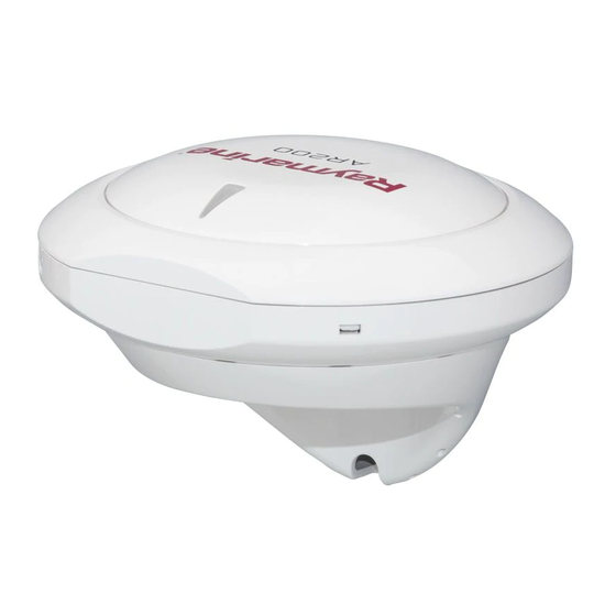
Page 10: Ar200 Product Overview
For more information about Augmented Reality and how it is used on your MFD, refer to 81370 LightHouse 3 Advanced operation instructions. The AR200 provides position, heading, pitch and roll data to compatible Axiom MFDs that are on the same SeaTalkng ® network. -
Page 11: Required Additional Components
• Waterproof to IPx6 and IPx7. 3.2 Required additional components The AR200 forms part of the ClearCruise™ Augmented Reality System and requires the following additional components to enable the Augmented Reality features on your system. Required components for Augmented Reality (IP cameras) •... -
Page 12: Multifunction Display Software Requirements
E70515 Axiom™ XL 24 E70401 Multifunction display software requirements The operation of this product requires that your MFD is running Raymarine LightHouse™ 3 software, version 3.7 or later. Note: • The latest MFD software can be obtained by visiting raymarine/software. -
Page 13: Chapter 4 Parts Supplied
Chapter 4: Parts supplied Chapter contents • 4.1 Parts supplied on page 20... -
Page 14: Parts Supplied
The following parts are supplied with your product. Mounting trim (Top). 2. Small sealing ring. 3. AR200. 4. 3 x large bulkhead bracket fixings (Pan head pozi DIN7981 ST 3.9x22 C Z A4 Stainless steel). 5. Mounting tray (Bottom). 6. 4 x small surface mount fixings (Pan head pozi DIN7981–ST 2.9x13 C Z A4 Stainless steel). -
Page 15: Chapter 5 Product Dimensions
Chapter 5: Product dimensions Chapter contents • 5.1 Product dimensions on page 22... -
Page 16: Product Dimensions
5.1 Product dimensions... -
Page 17: Chapter 6 Location Requirements
Chapter 6: Location requirements Chapter contents • 6.1 Selecting a location on page 24... -
Page 18: Selecting A Location
6.1 Selecting a location Warnings and cautions Important: Before proceeding, ensure that you have read and understood the warnings and cautions provided in the Chapter 1 Important information section of this document. Warning: Switch off power supply Ensure the vessel’s power supply is switched OFF before starting to install this product. -
Page 19: Rf Interference
• The unit can be mounted on a vertical surface such as a bulkhead or mast etc, using the supplied bulkhead bracket. • Do NOT mount on top of a mast. • The unit location must be at least 1 m (3 ft.) away from any source of magnetic interference, such as compasses and electrical cables. -
Page 20: Compass Safe Distance
EMC installation guidelines Raymarine equipment and accessories conform to the appropriate Electromagnetic Compatibility (EMC) regulations, to minimize electromagnetic interference between equipment and minimize the effect such interference could have on the performance of your system Correct installation is required to ensure that EMC performance is not compromised. -
Page 21: Chapter 7 Installation
Chapter 7: Installation Chapter contents • 7.1 Tools required for installation on page 28 • 7.2 Mounting on page 28... -
Page 22: Tools Required For Installation
7.1 Tools required for installation Power drill Suitable size drill bit (for Bulkhead bracket mounting) Note: Drill bit size is dependent on the type of material the unit is to be mounted on. 12 mm ( ”) drill bit (if required, for cable hole) Pozi-drive screwdriver 7.2 Mounting Bulkhead mounting... - Page 23 1. Use the supplied Bracket mounting template (87170) to drill 3 pilot holes in the vertical mounting surface. Secure the mounting bracket to the surface using the supplied screws. 2. Place the small sealing ring in the groove located on the bottom of the Mounting tray. 3.
- Page 24 7. Orientate the Mounting trim so that the release hole will be accessible once mounted. 8. Place the Mounting trim over the unit slightly offset, and then twist the Mounting trim clockwise until it locks into position.
-
Page 25: Surface Mounting
Surface mounting The supplied mounting bracket can be used to mount your product horizontally or vertically on a flat surface. The Bulkhead bracket is not required for this type of installation. Ensure that the chosen location meets the product’s location requirements, see 6.1 Selecting a location for details. - Page 26 7. Place the Mounting trim over the unit slightly offset, and then twist the Mounting trim clockwise until it locks into position.
-
Page 27: Surface Mounting Using The Riser
Surface mounting using the Riser The Deck mounting kit (A80437) can be used to raise the product from the mounting surface. The Wall bracket is not required when using the Riser. Ensure that the chosen location meets the product’s location requirements, see 6.1 Selecting a location for details. - Page 28 3. Position the Mounting tray on top of the Riser. 4. Secure the Mounting tray to the Riser using 3x supplied fixings. 5. Place the large sealing ring into the groove on the upper side of the Mounting tray. 6. Pull the SeaTalkng ® cable through the Riser and Mounting tray. Plug in the cable connector on the underside of the unit and secure by rotating the locking collar clockwise 2 clicks.
-
Page 29: Releasing The Unit From The Bracket
Releasing the unit from the bracket Follow the steps below to release the unit from the Mounting bracket. 1. Insert the flat of a small flat blade screw driver, or similar tool into the release hole located on the flat edge of the mounting bracket and twist the screw driver 90°, so that there is a small gap between the Mounting trim and Mounting tray. -
Page 30: Chapter 8 Connections
Chapter 8: Connections Chapter contents • 8.1 General cabling guidance on page 38 • 8.2 Connections overview on page 39 • 8.3 System example on page 40 • 8.4 SeaTalkng ® power supply on page 41... -
Page 31: General Cabling Guidance
• Unless otherwise stated only use cables supplied by Raymarine. • Where it is necessary to use non-Raymarine cables, ensure that they are of correct quality and gauge for their intended purpose. (e.g.: longer power cable runs may require larger wire gauges to minimize voltage drop along the run). -
Page 32: Connections Overview
8.2 Connections overview Your product includes the following connectors: 1 x SeaTalkng Male Connector Connects to: SeaTalk backbone 2. NMEA 2000 backbone Suitable cables: SeaTalk spur cables 2. SeaTalk to DeviceNet adaptor cable (A06045) Connecting SeaTalkng ® cables 1. Rotate your product’s SeaTalkng ® connector locking collar counter clockwise, so that the connector is in the unlocked position. -
Page 33: System Example
Below is a typical system example showing the components and connections required to enable ClearCruise™ Augmented Reality on your system. AR200. 2. SeaTalkng ® backbone (providing 12 V dc power to the AR200). 3. CAM210IP (CAM220IP is also compatible). 4. Axiom LightHouse™ 3 powered MFD (running LH3 version 3.7 or above). -
Page 34: Seatalkng ® Power Supply
8.4 SeaTalkng ® power supply Your product is supplied power via the SeaTalkng ® backbone. A SeaTalkng ® backbone requires a single 12 V dc power supply. Power can be supplied to the SeaTalkng ® backbone by one of the following methods: •... -
Page 35: In-Line Fuse And Thermal Breaker Ratings
• The information provided below is for guidance only, to help protect your product. It covers common vessel power arrangements, but does NOT cover every scenario. If you are unsure how to provide the correct level of protection, please consult an authorized Raymarine dealer or a suitably qualified professional marine electrician. - Page 36 SeaTalkng ® spur connector — connects to spur connection on the SeaTalkng ® network. 2. + Red (positive) wire — connects to battery or distribution panel positive terminal. 3. – Black (negative) wire — connects to battery or distribution panel negative terminal. 4.
- Page 37 Positive (+) bar 2. Negative (-) bar 3. Circuit breaker 4. Waterproof fuse holder with 5 A inline fuse must be fitted (not supplied). Important: Observe the recommended fuse / breaker ratings provided in the product’s documentation, however be aware that the suitable fuse / breaker rating is dependent on the number of devices being connected.
- Page 38 Waterproof fuse holder with 5 A inline fuse must be fitted (not supplied). 2. SeaTalkng ® power cable. 3. Drain wire connection point. Battery connection scenario A: Suitable for a vessel with a common RF ground point. In this scenario, the power cable’s drain wire should be connected to the vessel’s common RF ground point.
-
Page 39: Sharing A Breaker
• ABYC E-11 AC & DC Electrical Systems on Boats • ABYC A-31 Battery chargers and Inverters • ABYC TE-4 Lightning Protection Sharing a breaker Where more than 1 piece of equipment shares a breaker you must provide protection for the individual circuits. -
Page 40: Chapter 9 Setup And Calibration
Chapter 9: Setup and calibration Chapter contents • 9.1 Camera setup on page 48 • 9.2 AR200 Calibration (Linearization) on page 51... -
Page 41: Camera Setup
9.1 Camera setup Before using the Augmented Reality features, it’s important to correctly install and setup your compatible camera. Refer to your camera’s installation manual to determine the correct physical installation and connections for using the camera as part of an Augmented Reality system. A number of additional camera-related settings and calibrations must be completed in the Video app before Augmented Reality features can be used: •... -
Page 42: Pan And Tilt Camera Calibration
Menu item Options Camera height above waterline • 0m to 50m • 0ft to 165ft Camera direction • 0° (Forward) (default) • 0° to 180°p (Port) • 0° to 180°s (Starboard) • 30° to 120° Field of view • [CAM210IP – 53°] •... - Page 43 Note: Incorrect physical camera installation and incorrect settings provided in the camera setup page could result in an inaccurate Augmented Reality overlay. • To adjust the values of Camera height above waterline select the value box and adjust using the arrows. Menu item Options •...
-
Page 44: Ar200 Calibration (Linearization)
9.2 AR200 Calibration (Linearization) To enable accurate placement of Augmented Reality (AR) flags on the camera’s video feed, the AR200’s AHRS sensors need to compensate for local magnetic fields, as well as the Earth’s magnetic fields. Calibration is achieved using an automatic linearization process. The linearization process starts automatically after your vessel has turned approximately 100°, when travelling at a speed of between... -
Page 45: Magnetic Deviation
Red if the process is paused or otherwise interrupted. The time taken to complete the linearization process will vary according to the characteristics of the vessel, the AR200’s installation location, and the levels of magnetic interference present at the time linearization is performed. -
Page 46: Continual Monitoring And Adaptation
The maximum deviation reported during the last linearization process. Important: • If the Maximum deviation at last calibration is 45° or above, it is recommended that the AR200 unit is moved and re-installed in a location which is subject to less magnetic interference. Calibration in progress: While linearization is in progress the progress percentage is displayed. -
Page 47: Compass Lock
• rate-of-turn too slow or too fast Compass lock Once you are satisfied with the compass accuracy, you can lock the setting to prevent the system from completing a further automatic linearization in the future. This feature is particularly useful for vessels in environments that are exposed to strong magnetic disturbances on a regular basis (such as offshore wind farms or very busy rivers, for example). -
Page 48: Chapter 10 System Checks And Troubleshooting
Chapter 10: System checks and troubleshooting Chapter contents • 10.1 Augmented Reality (AR) initial test on page 56 • 10.2 GNSS (GPS) check on page 56 • 10.3 Troubleshooting on page 58... -
Page 49: Augmented Reality (Ar) Initial Test
3. AR Object detection range. 10.2 GNSS (GPS) check If you intend to use the AR200 as your system’s main GNSS (GPS) receiver, you may need to manually select it from the Data sources menu. The Data sources menu can be accessed from your Data master MFD: Homescreen > Settings >... - Page 50 Once selected, a tick is placed in the Preferred column and the Manual selection toggle switch will be enabled. If your AR200 has a position fix, position accuracy is displayed in the Value in use column. When a valid position fix is achieved, your vessel’s latitude and longitude position is displayed...
-
Page 51: Troubleshooting
If after referring to this section you are still having problems with your product, please refer to the Technical support section of this manual for useful links and Raymarine Product Support contact details. - Page 52 LED Sequence Status Bus not connected / fault Red LED flashes on twice every 4 seconds. Bus connected but not receiving data Red LED flashes on 7 times every 9 seconds.
-
Page 53: Gnss (Gps) Troubleshooting
GNSS (GPS) troubleshooting Potential problems with the GNSS (GPS) receiver and possible causes and solutions are described here. Problem Possible causes Possible solutions “No Fix” GNSS status Geographic location or Check periodically to see if a fix is obtained icon is displayed. prevailing conditions in better conditions or another geographic preventing satellite fix. -
Page 54: Augmented Reality (Ar) Troubleshooting
FOV. Check your camera’s documentation for FOV incorrectly. specifications. AR200 interference If your AR200 is installed in a location which includes a source of magnetic interference large enough to affect AR flag placement, you may need to re-install the AR200 in a different location. -
Page 55: Chapter 11 Operation
Chapter 11: Operation Chapter contents • 11.1 Operation instructions on page 64... -
Page 56: Operation Instructions
11.1 Operation instructions For detailed operation instructions for your product, refer to the documentation that accompanies your display. • 81370 — LightHouse 3 MFD Advanced Operation Instructions... -
Page 57: Chapter 12 Maintenance
Chapter 12: Maintenance Chapter contents • 12.1 Service and maintenance on page 66 • 12.2 Routine equipment checks on page 66 • 12.3 Product cleaning on page 66... -
Page 58: Service And Maintenance
12.1 Service and maintenance This product contains no user serviceable components. Please refer all maintenance and repair to authorized Raymarine dealers. Unauthorized repair may affect your warranty. 12.2 Routine equipment checks It is recommended that you perform the following routine checks, on a regular basis, to ensure the correct and reliable operation of your equipment: •... -
Page 59: Chapter 13 Technical Support
Chapter 13: Technical support Chapter contents • 13.1 Raymarine product support and servicing on page 68 • 13.2 Learning resources on page 70 • 13.3 Operation instructions on page 70... -
Page 60: Viewing Product Information (Lighthouse™ 3)
Viewing product information (LightHouse™ 3) Use the Settings menu to view hardware and software information about your MFD, and connected products. 1. Select Settings, from the Homescreen. The Getting started menu contains hardware and software information for your MFD. 2. You can view further information about your MFD, or view information about products networked using SeaTalkhs ®... - Page 61 ii. to display detailed diagnostics information for all products, select Product info from the Diagnostics pop over menu.
-
Page 62: Chapter 14 Technical Specification
Chapter 14: Technical specification Chapter contents • 14.1 Technical specification on page 72... -
Page 63: Technical Specification
14.1 Technical specification Power specification Nominal supply voltage: 12 V dc (Supplied by the SeaTalkng ® network.) Operating voltage range: 9 V dc to 16 V dc (protected up to 32 V dc) Power consumption: 30 mA Max. LEN (Load Equivalency Rating): Environmental specification Operating temperature range: -25 ºC to +55 ºC (-13 ºF to 131 ºF) -
Page 64: Ahrs Specification
Time to first fix from hot start: < 45 seconds Geodetic Datum: WGS–84 Antenna: Internal AHRS specification AHRS: • 3–Axis digital accelerometer • 3–Axis digital compass • 3–Axis MEMS Gyro digital angular rate sensor Magnetic compass accuracy: • Static = ≤1° RMS •... -
Page 65: Chapter 15 Spares And Accessories
Chapter 15: Spares and accessories Chapter contents • 15.1 Accessories on page 76 • 15.2 SeaTalkng ® cables and accessories on page 76... -
Page 66: Accessories
15.1 Accessories The following accessories are available: Accessories Item Part number Pole/rail mounting adaptor kit A80370 6 m SeaTalkng white spur cable A06072 A80437 Deck mounting (Clamshell/Riser) kit 15.2 SeaTalkng ® cables and accessories SeaTalkng ® cables and accessories for use with compatible products. SeaTalkng ®... - Page 67 4 x T-piece (A06028). Each T-piece allows connection of one SeaTalkng device. Multiple T-pieces can be ‘daisy chained’ together. 4. 2 x Backbone terminators (A06031). Terminators must be fitted to both ends of the SeaTalkng backbone. 5. 1 x 2 m (6.6 ft) Power cable (A06049). Used to provide 12 V dc power to the SeaTalkng backbone. Evolution autopilot cable kit (R70160) consists of: 1 x 5 m (16.4 ft) Backbone cable (A06036).
- Page 68 1 x 2 m (6.6 ft) Power cable (A06049). Used to provide 12 V dc power to the SeaTalkng backbone. 2. 1 x 1 m (3.3 ft) Spur cable (A06039). Used to connect a device to the SeaTalkng backbone. 3. 1 x 1 m (3.3 ft) NMEA 0183 VHF stripped-end (2 wire) to SeaTalkng adapter cable (A06071). Used to connect an NMEA 0183 VHF radio to the SeaTalkng backbone via the NMEA 0183 VHF to SeaTalkng converter.
- Page 69 4. SeaTalkng to stripped-end spur cables (Connects compatible product that do not have a SeaTalkng connector such as transducer pods): • 1 m (3.3 ft) SeaTalkng to stripped-end spur cable — A06043 • 3 m (9.8 ft) SeaTalkng to stripped-end spur cable — A06044 5.
- Page 70 5. Backbone terminator (A06031). Terminators must be fitted to both ends of the SeaTalkng backbone. 6. Spur blanking plugs (A06032). Used to cover unused spur connections in 5–way blocks, T-piece connectors, or the SeaTalk to SeaTalkng converter. Spur connector right angled elbow (A06077). Used in confined spaces where a straight spur cable will not fit.
- Page 71 10. (0.4 m (1.3 ft) DeviceNet (female) to stripped-end adaptor cable (E05026). 11. (0.4 m (1.3 ft) DeviceNet (male) to stripped-end adaptor cable (E05027).
-
Page 72: Appendix A Nmea 2000 Pgn Support
Appendix A NMEA 2000 PGN support The unit supports the following NMEA 2000 PGNs. Description Transmit (Tx) Receive (Rx) 59904 ISO Request ● 59392 ISO Acknowledgement ● 60160 ISO Transport protocol, data ● transfer 60416 ISO Transport protocol, Connection management — ●... - Page 73 SeaTalkng Power cables ........79 SeaTalkng spur cables ........78 AR200 ..............51 Calibration............52 Fuse rating, SeaTalkng ® ..........42 AR200, Product overview ........16 Augmented Reality Camera installation and setup ......48 Troubleshooting ..........61 Augmented Reality, camera FOV ......49 GNSS (GPS) ............. 57 Automatic linearization ..........53...
- Page 74 Parts supplied............20 Upgrading, See Software updates Position..............57 Power Battery connection..........44 Distribution ............42 Wall bracket.............28 Distribution panel..........43 Warranty ..............68 SeaTalkng power cable ........42 WEEE Directive............11 Sharing a breaker ..........43 Power cable extension ..........45 Power specification ..........72 Product dimensions, See Dimensions Product information ..........69 Product loading ............39...
Need help?
Do you have a question about the AR200 and is the answer not in the manual?
Questions and answers