Advertisement
Quick Links
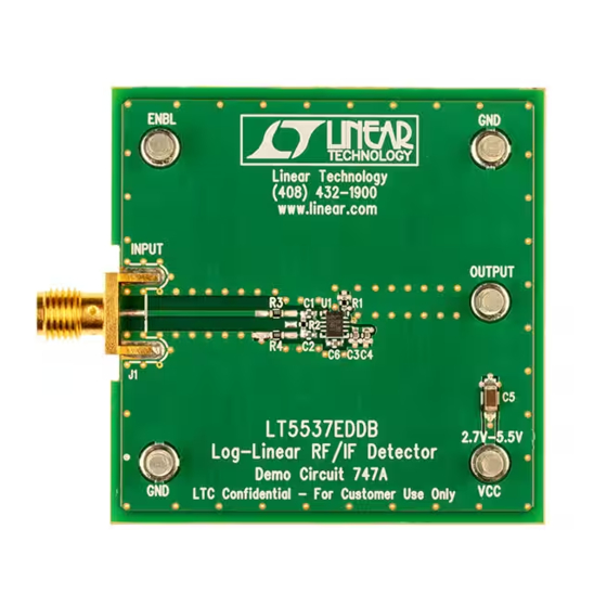
QUICK START GUIDE FOR DEMONSTRATION CIRCUIT 747
DESCRIPTION
Demonstration circuit 747 is a log-linear RF/IF detector
®
featuring the LT
5537.
The LT5537 is a wide dynamic range RF/IF log detec-
tor, operational from below 10MHz to 1000MHz. The
lower limit of the operating frequency range can be
extended to near DC by the use of an external capaci-
tor. The input dynamic range at 200MHz with ±3dB
nonlinearity is 90dB (from –76dBm to 14dBm, single-
Table 1. Typical Performance Summary (V
PARAMETER
Supply Voltage
Supply Current
Shutdown Current
ENBL Voltage
ENBL Input Current
RF/IF Input DC Common Mode Voltage
Small-Signal Impedance
Output Start Voltage
Response Time
Baseband Modulation Bandwidth
Input Frequency Range
Maximum Input Power for
Monotonic Output
f = 10MHz
Linear Dynamic Range
Slope
Intercept
Sensitivity
Temperature Coefficient
= 3V, ENBL = 3V, T
A
CC
CONDITION
ENBL = Low
Low, Chip Disabled
High, Chip Enabled
V
= 0V
ENBL
V
= 3V
ENBL
Measured at 200MHz
No Input Signal Present
Input from –30dBm to 0dBm, C
Output Load Capacitance = 2.5pF
Operation at lower frequency is possible. See LT5537 datasheet.
50Ω Termination
200MHz
600MHz
1GHz
±3dB Error
±1dB Error
R1 = 33k (The output slope is adjustable using R1.)
V
= 0V, extrapolated
OUT
Sensitivity can be improved by as much as 10dB by using a narrow-
band input matching network. See LT5537 datasheet.
P
= -20dBm
IN
LOG-LINEAR RF/IF DETECTOR
ended 50Ω input). The detector output voltage slope
is normally 20mV/dB, and the typical temperature
coefficient is 0.01dB/°C at 200MHz.
Design files for this circuit board are available. Call
the LTC factory.
LTC is a trademark of Linear Technology Corporation
= 25°C, unless otherwise noted. Test circuit shown in Figure 1.)
= 2.5pF
LOAD
LT5537
VALUE
2.7V to 5.25V
13.5mA
500µA
0.3V max
1.0V min
0µA
100µA
(V
– 0.4) V
CC
1.73kΩ // 1.45pF
0.4V
110ns
6MHz
10MHz to 1GHz
14.0dBm
11.6dBm
9.4dBm
88.8dB
72.5dB
19.6mV/dB
-97dBm
-76.7dBm
-0.007dB/°C
1
Advertisement

Related Manuals for Linear 747


Summary of Contents for Linear 747
- Page 1 QUICK START GUIDE FOR DEMONSTRATION CIRCUIT 747 LOG-LINEAR RF/IF DETECTOR LT5537 DESCRIPTION ended 50Ω input). The detector output voltage slope Demonstration circuit 747 is a log-linear RF/IF detector is normally 20mV/dB, and the typical temperature ® featuring the LT 5537.
- Page 2 QUICK START GUIDE FOR DEMONSTRATION CIRCUIT 747 LOG-LINEAR RF/IF DETECTOR f = 100MHz ±3dB Error 90.5dB Linear Dynamic Range ±1dB Error 82.8dB Slope R1 = 33k (The output slope is adjustable using R1.) 20.3mV/dB Intercept = 0V, extrapolated -95dBm Sensitivity can be improved by as much as 10dB by using a narrow-...
-
Page 3: Quick Start Procedure
QUICK START GUIDE FOR DEMONSTRATION CIRCUIT 747 LOG-LINEAR RF/IF DETECTOR QUICK START PROCEDURE Demonstration circuit 747 is easy to set up to evalu- Connect signal generator’s output to demo board ate the performance of the LT5537. Refer to Figure 1 INPUT port (SMA connector J1) via coaxial cable. - Page 4 QUICK START GUIDE FOR DEMONSTRATION CIRCUIT 747 LOG-LINEAR RF/IF DETECTOR...
- Page 5 Mouser Electronics Authorized Distributor Click to View Pricing, Inventory, Delivery & Lifecycle Information: Analog Devices Inc. DC747A...
Need help?
Do you have a question about the 747 and is the answer not in the manual?
Questions and answers