Table of Contents
Advertisement
Quick Links
U
DESCRIPTIO
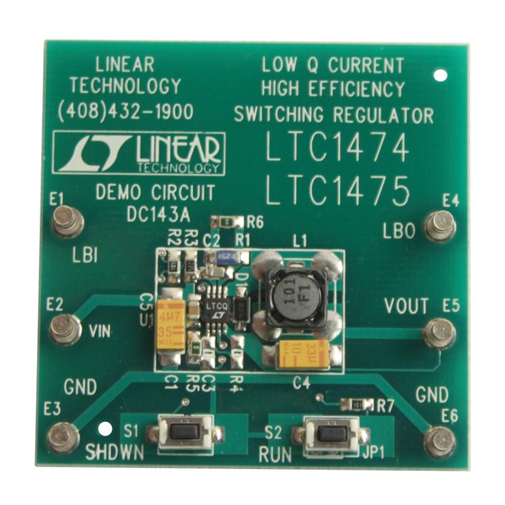
This demonstration circuit is a step-down (buck) regulator
®
using the LTC
1474/LTC1475. The exclusive use of surface
mount components and the LTC1474/LTC1475 in the tiny
MSOP package results in a highly efficient application in a
small board space. This demo board highlights the
capabilities of the LTC1474/LTC1475, which use a current
mode, constant off-time architecture to switch an internal
P-channel power MOSFET. This results in a power supply
that has low ripple and fast transient response. At low
output currents the LTC1474/LTC1475 automatically
TM
switch to Burst Mode
Operation to maintain high operating
efficiencies and minimize supply current. At no load,only
PERFORmANCE SU
SYMBOL
PARAMETER
V
Input Voltage Range
IN
V
Output Voltage
OUT
I
Maximum Output Current
OUT
I
Typical Supply Current
Q
TYPICAL PERFOR A CE CHARACTERISTICS A D BOARD PHOTO
Board A, B, D, E Efficiency
100
V
= 5V
IN
90
V
= 10V
IN
80
V
= 15V
IN
70
60
50
0.03
0.3
3
LOAD CURRENT (mA)
ARY
CONDITIONS
V
= 3.3V
OUT
V
= 5V
OUT
LTC1474/LTC1475
LTC1474-3.3/LTC1475-3.3
LTC1474-5/LTC1475-5
R
SENSE
R
SENSE
V
= 10V, I
IN
V
= 10V, I
IN
W
U
L = 100µH
V
= 3.3V
OUT
R
= 0Ω
SENSE
30
300
DM143 TPC
DEMO MANUAL DC143
DEMO MANUAL DC143
10µA I
10µA (typical) is required to regulate the output. The parts
can be shut down to further reduce the supply current to
6µA (typical). In dropout, the internal P-channel MOSFET
is turned on continuously (100% duty cycle), providing
low dropout operation with V
battery detector allows the user to monitor the input
supply through an external resistive divider. This board is
intended for applications such as cellular phones, GSM
systems, 4mA to 20mA current-loop pirate supplies or any
portable battery-powered application. Gerber files for this
circuit board are available. Call the LTC factory.
, LTC and LT are registered trademarks of Linear Technology Corporation.
Burst Mode is a trademark of Linear Technology Corporation.
= 0Ω
= 0.25Ω
= 0
LOAD
= 0
LOAD
U
Demo Board A
DM143 DB A
NO DESIGN SWITCHER
LTC1474/LTC1475
, High Efficiency,
Q
Step-Down DC/DC
Converter
≅ V
. An onboard low-
OUT
IN
BOARD SUFFIX
VALUE
A, B, D, E
3.3V to 18V
C, F
5V to 18V
3.3V ± 0.10V
A, D
3.3V ± 0.10V
B, E
5V ± 0.15V
C, F
ALL
300mA
ALL
150mA
A, B, C
10µA
D, E, F
15µA
Demo Board D
DM143 DB D
1
Advertisement
Table of Contents

Subscribe to Our Youtube Channel
Related Manuals for Linear LTC1474


Summary of Contents for Linear LTC1474
- Page 1 Call the LTC factory. efficiencies and minimize supply current. At no load,only , LTC and LT are registered trademarks of Linear Technology Corporation. Burst Mode is a trademark of Linear Technology Corporation. PERFORmANCE SU...
- Page 2 *ADJUSTABLE OUTPUT VERSION LTC1474 100µH 6.3V LTC1474CMS8 LTC1474CMS8-3.3 100k LTC1474CMS8-5 MBR0530 *3.3V AT NO LOAD DM143 F01 Figure 1. LTC1474 Demo Board Schematic TOP VIEW THIS NETWORK IS PRESENT IN 4V* TO 18V 10pF BOARD D ONLY LBI/OFF SENSE 4.7µF 1000pF 0.1µF...
-
Page 3: Parts List
(803) 946-0524 S1, S2 EVQ PJS05K Momentary Switch (Boards D, E, F) Panasonic (201) 392-4511 LTC1474CMS8 8-Pin MSOP IC, LTC1474 (Board A) (408) 432-1900 LTC1474CMS8-3.3 8-Pin MSOP IC, LTC1474-3.3 (Board B) LTC1474CMS8-5 8-Pin MSOP IC, LTC1474-5 (Board C) LTC1475CMS8 8-Pin MSOP IC, LTC1475 (Board D) LTC1475CMS8-3.3... -
Page 4: Quick Start Guide
Operation The LTC1474/LTC1475 also provide user-programmable The LTC1474/LTC1475 use a current mode, constant off- peak inductor current: the user can set the peak current to time architecture shown in Figure 3. Current mode opera-... - Page 5 1.23V REFERENCE LTC1474: LBI LTC1475: LBI/OFF × CONNECTION NOT PRESENT IN LTC1474 SERIES DM143 F03 CONNECTION PRESENT IN LTC1474 SERIES ONLY Figure 3. LTC1474/LTC1475 Block Diagram The demo board includes two sense resistors; 0.25Ω R1 is shorted out with a 0Ω resistor (R6) to easily demonstrate peak current programming.
- Page 6 This information occurs between Pins 1 selection criteria for most of the external components and 4 of the LTC1474/LTC1475. These points correspond surrounding the IC. Be sure to refer to the data sheet if to the output terminals of the demonstration board. Test changes to this demo circuit are anticipated.
- Page 7 Information furnished by Linear Technology Corporation is believed to be accurate and reliable. However, no responsibility is assumed for its use. Linear Technology Corporation makes no represen- tation that the interconnection of its circuits as described herein will not infringe on existing patent rights.
- Page 8 5. SILKSCREEEN COMPONENT SIDE 6. ALL HOLE SIZES AFTER PLATING + 0.003/ –0 dc143 LT/TP 0697 500 • PRINTED IN USA Linear Technology Corporation 1630 McCarthy Blvd., Milpitas, CA 95035-7417 (408) 432-1900 FAX: (408) 434-0507 TELEX: 499-3977 www.linear-tech.com © LINEAR TECHNOLOGY CORPORATION 1997...
Need help?
Do you have a question about the LTC1474 and is the answer not in the manual?
Questions and answers