Table of Contents
Advertisement
Quick Links
DESCRIPTION
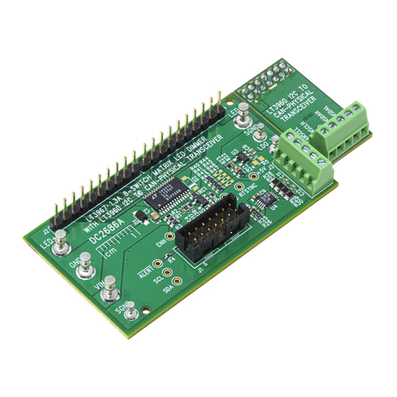
Demonstration circuit 2686A is a 1.3A 8-switch matrix LED
dimmer system with an I
featuring the
LT
3967
and LT3960. This demonstration
®
circuit connects directly to a LED string and LED driver
demonstration circuit to allow for independent dimming
control of up to 8 channels of LEDs. A Linduino
demonstration circuit is used to interface with the board
and can connect in one of two different ways:
1. Connect directly to a Linduino One demonstration
circuit with a QuikEval™ ribbon cable.
2. Connect using the LT3960 break-off board to con-
2
nect to the I
C master device, but pass data over two
twisted pair lines to the LT3960 on the main PCB.
The LT3967 matrix dimmer features 8 individually con-
trolled 1.3A rated floating NMOS switch channels and can
support up to 56V of LEDs per device. The channels of
the LT3967 can be configured for series connections, or
non-series connections. Additional DC2686A demo cir-
cuits can be connected in series for higher number of
LEDs, or in parallel to allow for higher current operation.
Resistors are used to configure both the I
as well as the default start-up state. The default configu-
ration for DC2686A sets the I
LEDs off. See the LT3967 data sheet for details.
1.3A 8-Switch Matrix LED Dimmer with I
to CAN-Physical Layer Transceiver
2
C to CAN-physical transceiver
2
C slave address
2
C address as 0000 with all
DEMO MANUAL DC2686A
2
The LT3960 I
send and receive I
ronments at up to 400kb/s using the CAN-Physical layer
for differential signaling over twisted pair connections.
Both SDA and SCL data lines are converted to differential
One
signals and are shared between devices connected to the
®
bus. This allows for physical separation of the I
with the LT3960 transceiver board and the LT3967 main
PCB along with the LED driver.
This demo circuit is designed to be easily configured and
interfaced with a compatible low output capacitance LED
driver and LED string. It can easily be directly attached
to a buck LED driver or a floating buck-mode LED driver.
More sophisticated setups with series matrix dimmers
for higher number of LEDs such as 12 or 16 is possible.
Please consult factory applications for details or look for
more details on analog.com.
The LT3967 and LT3960 data sheets give complete
description of the parts, their operation and applications
information. The data sheets must be read in conjunc-
tion with this demo manual for demonstration circuit
DC2686A. The LT3967EFE is assembled in a thermally
enhanced 28-lead TSSOP package. The LT3960EMSE is
assembled in a 10-lead MSOP package.
Design files for this circuit board are
All registered trademarks and trademarks are the property of their respective owners.
LT3967/LT3960
C to CAN-Physical transceiver is used to
2
C data through harsh or noisy envi-
available.
2
C
2
C source
Rev. 0
1
Advertisement
Table of Contents

Related Manuals for Linear Analog Devices LT3960


Summary of Contents for Linear Analog Devices LT3960
- Page 1 DEMO MANUAL DC2686A LT3967/LT3960 1.3A 8-Switch Matrix LED Dimmer with I to CAN-Physical Layer Transceiver DESCRIPTION Demonstration circuit 2686A is a 1.3A 8-switch matrix LED The LT3960 I C to CAN-Physical transceiver is used to dimmer system with an I C to CAN-physical transceiver send and receive I C data through harsh or noisy envi-...
-
Page 2: Performance Summary
DEMO MANUAL DC2686A PERFORMANCE SUMMARY Specifications are at T = 25°C PARAMETER CONDITION UNIT Input Voltage LT3967, Operating LT3960, Operating LED Voltage LT3967, Operating LED Current LT3967, Operating LT3967 ENH Threshold Falling Voltage (V – ENH) R1 = 10k, R2 = 49.9k 1.10 1.22 1.34... - Page 3 DEMO MANUAL DC2686A QUICK START PROCEDURE Figure 1. Quick-Start Procedure Setup Drawing for DC2686A (without LT3960) *SNAP OFF SMALL BOARD FROM THE MAIN BOARD TO SET UP VIA LT3960 Figure 2. Quick Start Procedure Setup Drawing for DC2686A (with LT3960) Rev. 0...
- Page 4 DEMO MANUAL DC2686A BOARD OPTIONS SETUP DIFFERENCES BETWEEN BUCK VS BUCK-MODE UTILIZING LT3960 FOR SERIAL COMMUNICATION When using DC2686A with a buck LED driver, connect the The LT3960 can be used to communicate with the of the buck LED driver directly to V of LT3967, and LT3967 over longer distances and/or in noisy environ- ensure that V...
-
Page 5: Board Options
DEMO MANUAL DC2686A BOARD OPTIONS Figure 3. Arduino COM Terminal Window; Selectable Options Menu Rev. 0... - Page 6 DEMO MANUAL DC2686A BOARD OPTIONS 1µF 1µF 100V 100V 49.9k 49.9k ADDR1 ADDR1 LT3967 LT3967 ADDR2 ADDR2 ADDR3 ADDR3 ADDR4 ADDR4 0.1µF 0.1µF – ALERT ALERT ALERT ALERT RTSLK RTSLK EXTERNAL DC2786A F04 CLOCK SOURCE Figure 4. Two Series-Connected LT3967 ICs Rev.
-
Page 7: Test Results
DEMO MANUAL DC2686A TEST RESULTS − Figure 5. Thermal Capture of DC2686A at 50V , 8 Channels Shorted Through IC at 1.3A. LED = 1.2V, LED = 0V Rev. 0... - Page 8 RES., OPTION, 0805 RES., 392k, 1%, 1/10W, 0603, AEC-Q200 VISHAY, CRCW0603392KFKEA RES., 127k, 1%, 1/10W, 0603, AEC-Q200 VISHAY, CRCW0603127KFKEA RES., 0Ω, 1/10W, 0603, AEC-Q200 VISHAY, CRCW06030000Z0EA IC, LDO MICROPOWER LINEAR REG., SOT23-5, 20mA, ANALOG DEVICES, LT3014IS5#PBF 3V TO 80V Rev. 0...
-
Page 9: Parts List
DEMO MANUAL DC2686A PARTS LIST ITEM REFERENCE PART DESCRIPTION MANUFACTURER/PART NUMBER Hardware E1, E2, E3, E4 TEST POINT, TURRET, 0.094" MTG. HOLE, PCB 0.062" THK MILL-MAX, 2501-2-00-80-00-00-07-0 E5, E6, E7 TEST POINT, TURRET, 0.064" MTG. HOLE, PCB 0.062" THK MILL-MAX, 2308-2-00-80-00-00-07-0 CONN., HDR, SHROUDED, MALE, 2×7, 2mm, VERT, ST, THT MOLEX, 87831-1420 J2, J4 CONN., HDR, MALE, 1×10, 2.54mm, VERT, ST, THT... - Page 10 DEMO MANUAL DC2686A SCHEMATIC DIAGRAM Rev. 0...
-
Page 11: Schematic Diagram
DEMO MANUAL DC2686A SCHEMATIC DIAGRAM Rev. 0 Information furnished by Analog Devices is believed to be accurate and reliable. However, no responsibility is assumed by Analog Devices for its use, nor for any infringements of patents or other rights of third parties that may result from its use. Specifications subject to change without notice. - Page 12 DEMO MANUAL DC2686A ESD Caution ESD (electrostatic discharge) sensitive device. Charged devices and circuit boards can discharge without detection. Although this product features patented or proprietary protection circuitry, damage may occur on devices subjected to high energy ESD. Therefore, proper ESD precautions should be taken to avoid performance degradation or loss of functionality. Legal Terms and Conditions By using the evaluation board discussed herein (together with any tools, components documentation or support materials, the “Evaluation Board”), you are agreeing to be bound by the terms and conditions set forth below (“Agreement”) unless you have purchased the Evaluation Board, in which case the Analog Devices Standard Terms and Conditions of Sale shall govern.
- Page 13 Mouser Electronics Authorized Distributor Click to View Pricing, Inventory, Delivery & Lifecycle Information: Analog Devices Inc. DC2686A...
Need help?
Do you have a question about the Analog Devices LT3960 and is the answer not in the manual?
Questions and answers