Table of Contents
Advertisement
Quick Links
LI1B Series
User's Manual
NO. G03-LI1B-F
Revision: 1.0
Release date: December 10, 2021
Trademark:
* Specifications and Information contained in this documentation are furnished for information use only, and are
subject to change at any time without notice, and should not be construed as a commitment by manufacturer.
Advertisement
Table of Contents

Related Manuals for JETWAY LI1B Series


Summary of Contents for JETWAY LI1B Series
- Page 1 LI1B Series User’s Manual NO. G03-LI1B-F Revision: 1.0 Release date: December 10, 2021 Trademark: * Specifications and Information contained in this documentation are furnished for information use only, and are subject to change at any time without notice, and should not be construed as a commitment by manufacturer.
- Page 2 Environmental Protection Announcement Do not dispose this electronic device into the trash while discarding. To minimize pollution and ensure environment protection of mother earth, please recycle.
-
Page 3: Table Of Contents
TABLE OF CONTENT ENVIRONMENTAL SAFETY INSTRUCTION ..............iii USER’S NOTICE ........................iv MANUAL REVISION INFORMATION .................. iv ITEM CHECKLIST ........................ iv CHAPTER 1 INTRODUCTION OF THE MOTHERBOARD FEATURE OF MOTHERBOARD ................1 SPECIFICATION ......................2 LAYOUT DIAGRAM ....................3 CHAPTER 2 HARDWARE INSTALLATION JUMPER SETTING ..................... -
Page 4: Environmental Safety Instruction
Environmental Safety Instruction ⚫ Avoid the dusty, humidity and temperature extremes. Do not place the product in any area where it may become wet. ⚫ 0 to 40 centigrade is the suitable temperature. (The temperature comes from the request of the chassis and thermal solution) ⚫... -
Page 5: User's Notice
USER’S NOTICE COPYRIGHT OF THIS MANUAL BELONGS TO THE MANUFACTURER. NO PART OF THIS MANUAL, INCLUDING THE PRODUCTS AND SOFTWARE DESCRIBED IN IT MAY BE REPRODUCED, TRANSMITTED OR TRANSLATED INTO ANY LANGUAGE IN ANY FORM OR BY ANY MEANS WITHOUT WRITTEN PERMISSION OF THE MANUFACTURER. -
Page 6: Chapter 1 Introduction Of The Motherboard Feature Of Motherboard
Chapter 1 Introduction of the Motherboard Feature of Motherboard ⚫ Onboard Intel ® ElkhartLake series processor ⚫ Support 1* DDR4 3200MHz SO-DIMM up to 16GB and single channel function ⚫ Integrated with 2* Intel i211AT Gigabit Ethernet LAN chip ⚫ Support 2* USB 3.1(Gen.1) & 7* USB2.0 data transport demand ⚫... -
Page 7: Specification
1-2 Specification Spec Description ⚫ Mini-ITX form factor 6 layers; PCB size: 17.0x17.0cm Design ⚫ Integrated Intel ® ElkhartLake series CPU Embedded CPU * for detailed CPU support information please visit our website ⚫ 1*DDR4 SO-DIMM slot support 1* DDR4 3200MHz up to 16GB Memory Slot ⚫... -
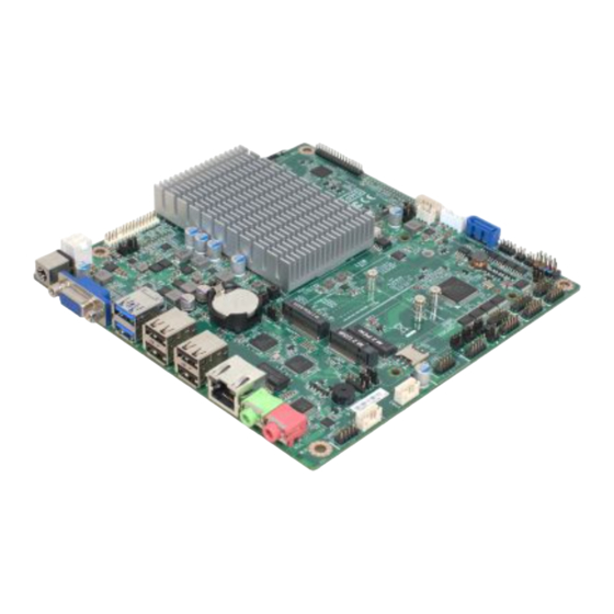
Page 8: Layout Diagram
⚫ Model LI1B-00: 2* 9-Pin USB 2.0 header ⚫ Model LI1B-0L: 1* 9-Pin USB 2.0 headers ⚫ 1* 4-Pin USB 2.0/1.1 wafer for 1* USB 2.0/1.1 ports ⚫ 1* SMBUS header ⚫ 1* GPIO header ⚫ 6* Serial port header (COM3/4/5/6 support RS232, COM1/2 support RS232/422/485) ⚫... - Page 9 Motherboard Internal Diagram-Front For LI1B-00 Series: 12V DC EDP Connector Power Connector 12V DC-in Jack LVDS Connector VGA port *DDR4 SODIMM Slot USB 3.1(Gen.1) Ports Inverter Connector USB 2.0 Ports CPUFAN Connector SATA power Connector M.2 M-key (M2M1) SATAIII Port (SATA1) RJ-45 LAN Port M.2 E-key...
- Page 10 For LI1B-0L Series: 12V DC EDP Connector Power Connector 12V DC-in Jack LVDS Connector VGA port *DDR4 SODIMM Slot USB 3.1(Gen.1) Ports USB 2.0 Headers (FP_USB2) USB 2.0 Ports Inverter Connector CPUFAN Connector SATA power Connector M.2 M-key (M2M1) RJ-45 LAN Ports SATAIII Port (SATA1) M.2 E-key...
- Page 11 Motherboard Jumper Position JPLCD2 JPBKLT2 JPBKLT1 JPLCD1 M2M_PWR1 JPCLR1 JPCOM1 TX-RXCOM1 M2B_PWR1 JPCOM2 TX-RXCOM2 JP80P1 JPCOM3 AT_MODE M2E_PWR1 JPCOM4...
- Page 12 Jumper Jumper Name Description JPCOM1 COM1 Port Pin9 Function Select 4-pin Block (2.0 pitch) JPCOM2 COM2 Port Pin9 Function Select 4-pin Block (2.0 pitch) JPCOM3 COM3 Port Pin9 Function Select 4-pin Block (2.0 pitch) JPCOM4 COM4 Port Pin9 Function Select 4-pin Block (2.0 pitch) M2M1 Connector Function Select...
- Page 13 USB4 USB 2.0 Port Connector X2 *Option for LI1B-00 Series RJ-45 LAN Connector X1 *Option for LI1B-0L Series LAN1 RJ-45 LAN Connector LINE-OUT Line-out Connector MIC Connector SPEAK_CON1 3W Amplifier Connector SIMCARD SIM card slot SATA1 SATAIII Connector SATAPWR1 SATA Power out Connector CPUFAN1 FAN Connector Light Control Connector...
-
Page 14: Chapter 2 Hardware Installation
Chapter 2 Hardware Installation 2-1 Jumper Setting JPCOM1/2/3/4 (4-pin): COM1/2/3/4 Port Pin9 Function Select (2.0 pitch) → JPCOM1 COM1 Port Pin-9 → JPCOM2 COM2 Port Pin-9 → JPCOM3 COM3 Port Pin-9 → JPCOM4 COM4 Port Pin-9 JPCOM2 JPCOM3 1 3 5 JPCOM4 JPCOM1 2-4 Closed:... - Page 15 JPLCD (6-pin): LCD Panel VCC Select (2.0 pitch) JPLCD1 JPLCD2 → JPLCD1 LCD Panel VCC Select → JPLCD2 LCD Panel VCC Select 1 3 5 2-4 Closed: 3-4 Closed: 4-6 Closed: VCC=+12V; VCC=+5V; VCC=+3.3V JPBKLT1 (3-pin): LCD BACKLIGHT VCC Select (2.0 pitch) →...
- Page 16 JPBKLT2 (3-pin): LCD BACKLIGHT VCC Select (2.0 pitch) → JPBKLT2 LCD BACKLIGHT VCC Select 2-3 Closed: 1-2 Closed: VCC= +5V VCC= +12V Pin (1-2) of JPCLR1 (8-pin): Clear ME_RTC (2.0 pitch) PIN(1-2) Clear ME_RTC Pin1 1-2 Open: Normal(Default) Pin1 1-2 Closed: Clear ME_RTC...
- Page 17 Pin (3-4) of JPCLR1 (8-pin): Clear CMOST (2.0 pitch) PIN(3-4) Clear CMOST Pin1 3-4 Open: Normal(Default) Pin1 3-4 Closed: Clear CMOST Pin (5-6) of JPCLR1 (8-pin): TXE Override (2.0 pitch) PIN(5-6) TXE Override Pin1 5-6 Open: Normal(Default) Pin1 5-6 Closed: TXE Override...
- Page 18 Pin (7-8) of JPCLR1 (8-pin): CASE OPEN (2.0 pitch) PIN(7-8) CASE OPEN Pin1 7-8 Open: Normal(Default) Pin1 7-8 Closed: CASE OPEN M2M_PWR1 (3-pin): M.2 M-key Power Select (2.0 pitch) → M2M_PWR1 M.2 M-key Power Select 1-2 Closed: 2-3 Closed: VCC= 3VSB VCC= VCC3...
- Page 19 M2B_PWR1 (3-pin): M.2 B-key Power Select (2.0 pitch) → M2B_PWR1 M.2 B-key Power Select 1-2 Closed: 2-3 Closed: VCC= VCC3 VCC= 3VSB M2E_PWR1 (3-pin): M.2 E-key Power Select (2.0 pitch) → M2E_PWR1 M.2 E-key Power Select 1-2 Closed: 2-3 Closed: VCC= 3VSB VCC= VCC3...
- Page 20 JP80P1 (2-pin): GPIO/80 Port Function Select (2.0 pitch) Pin1 1-2 Open: GPIO1=80 Port Pin1 1-2 Closed: GPIO1=GPIO Port AT_MODE(3-pin): ATX Mode/AT Mode Select (2.0 pitch) → AT_MODE ATX Mode/AT Mode Select 1-2 Closed: 2-3 Closed: AT MODE ATX MODE *ATX Mode Selected: Press power button to power on after power input ready; AT Mode Selected: Directly power on as power input ready.
-
Page 21: Connectors And Headers
2-2-1 Connectors (1) Rear Panel Connectors * Refer to Page-3 Rear IO Diagram. Icon Name Function 12V DC-in For user to connect compatible power adapter to Power Jack provide power supply for the system. To connect display device that support VGA specification. - Page 22 (2) ATX12V1 (4-pin block): ATX12V Type Power Connector Pin2 Pin1 Pin4 Pin No. Definition +12V +12V (3) SATA1 (7-pin): SATA III Port connector SATA1 are high-speed SATAIII port that supports 6 GB/s transfer rate. Pin No. Defnition...
- Page 23 (4) SATAPWR (4-pin): SATA HDD Power-Out Connector Pin 1 +12V (5) USB3 (4-pin): USB 2.0 Connector Pin 1...
- Page 24 (6) JP1 (3-pin): Light Control Connector BRTNSS_DOWN Pin 1 BRTNSS_UP (7) SPEAK_CON1 (4-pin): 3W Amplifier Connector Pin 1...
-
Page 25: Headers
(8) CPUFAN1 (4-pin): Fan Connector (2.54 pitch) Pin1 CPUFAN1 2-2-2 Headers (1) JW_FP1 (9-pin): Front Panel Header (2.54 pitch) Pin 1 HDD LED+ PWR LED+ HDD LED PWR LED - PWRSW RSTSW... - Page 26 (2) FP_AUDIO1 (9-pin): Line-Out, MIC-In Header (2.0 pitch) Pin1 (3) FP_USB1 (9-pin): USB 2.0 Port Headers (2.0 pitch) FP_USB1 → USB 2.0 Port *2 Pin 1...
- Page 27 (4) FP_USB2 (9-pin): USB 2.0 Port Headers (2.0 pitch) *Option for LI1B-00 Series FP_USB2 → USB 2.0 Port *2 Pin1 -DATA -DATA +DATA +DATA (5) SMBUS (5-Pin): SMBUS Header (2.0 pitch) Pin1 SMBUS_CLK SMBUS_DATA SMBUS_ALERT VCC3...
- Page 28 (6) GPIO1(10-pin): GPIO Header (2.0 pitch) Pin 1 (7) COM1/COM2 (9-pin): RS232/422/485 Serial Port Header (2.0 pitch) Pin NO. RS232 *RS422 *RS485 (optional) (optional) Pin 1 DATA- COM1 Pin 2 DATA+ Pin 3 Pin 4 Pin 5 COM2 Pin 6 Pin 7 Pin 8 Pin 9...
- Page 29 (8) COM3/COM4/COM5/COM6 (9-pin): RS232 Serial Port Header (2.0 pitch) Pin NO. RS232 Pin 1 Pin 2 COM3 COM5 Pin 3 SOUT Pin 4 Pin 5 COM4 COM6 Pin 6 Pin 7 Pin 8 Pin 9 2 3 4 5 Pin 1 (9) TX-RXCOM1 (4-pin): COM Port1 RS422/RS485 (2.0 pitch) Pin1...
- Page 30 (10) TX-RXCOM2 (4-pin): COM Port2 RS422/RS485 (2.0 pitch) Pin1 TXD1 TXD1- RXD1 RXD1- (11) INVERTER1 (6-pin): LVDS Inverter Connector (2.0 pitch) Pin No. Definition Backlight PWM Backlight Enable Pin1 Backlight Power Backlight Power...
- Page 31 (12) EDP2(30-pin): EDP Connector (2.0 pitch) Pin 2 Pin1 Pin No. Pin Define Pin No. Pin Define Pin 2 BKLT2_PWR Pin 1 BKLT2_PWR Pin 4 Pin 3 BKLT2_PWR Pin 6 Pin 5 Pin 8 EDP2_SCL Pin 7 Pin 10 EDP2_SDA Pin 9 Pin 12 Pin 11...
- Page 32 (13) LVDS1 (30-pin): 24-bit Dual Channel LVDS Header (2.0 pitch) Pin2 Pin1 Pin Define Pin NO. Pin NO. Pin Define LVDSB_DATAP3 Pin 30 Pin 29 LVDSB_DATAN3 LVDS_CLKBP Pin 28 Pin 27 LVDS_CLKBN Pin 26 Pin 25 LVDSB_DATAP2 Pin 24 Pin 23 LVDSB_DATAN2 LVDSB_DATAP1 Pin 22...
-
Page 33: Chapter 3 Introducing Bios
Chapter 3 Introducing BIOS Notice! The BIOS options in this manual are for reference only. Different configurations may lead to difference in BIOS screen and BIOS screens in manuals are usually the first BIOS version when the board is released and may be different from your purchased motherboard. Users are welcome to download the latest BIOS version form our official website. -
Page 34: Bios Menu Screen
BIOS Menu Screen The following diagram show a general BIOS menu screen: Menu Bar General Help Items Current Setting Value Menu Items Function Keys... -
Page 35: Function Keys
Function Keys In the above BIOS Setup main menu of, you can see several options. We will explain these options step by step in the following pages of this chapter, but let us first see a short description of the function keys you may use here: ⚫... -
Page 36: Main Menu
Chipset To change chipset configuration Security Password settings Boot To change boot settings Save & Exit Save setting, loading and exit options. User can press the right or left arrow key on the keyboard to switch from menu bar. The selected one is highlighted. Main Menu Main menu screen includes some basic system information. -
Page 37: Advanced Menu
3-7 Advanced Menu CPU Configuration Press [Enter] to make settings for the following sub-items: Intel(R) SpeedStep(tm) This item allows more than two frequency ranges to be supported. The optional settings are: [Disabled]; [Enabled]. When set as [Enabled], user can make further setting in the following item: Turbo Mode Use this item to enable or disable processor Turbo Mode (requires EMTTM enabled too). - Page 38 Enhanced C-states Use this item to enable or disable C1E. When set as [Enabled], CPU will switch to minimum speed when all cores enter C-State. The optional settings are: [Disabled]; [Enabled]. Package C State Limit Use this item to select the Maximum Package C State Limit Setting. The optional settings are: [C0/C1];...
- Page 39 Trusted Computing Press [Enter] to enable or disable Security Device Support. TPM 2.0 Device Found Security Device Support Use this item to enable or disable BIOS support for security device. O.S. will not show Security Device. TCG EFI protocol and INT1A interface will not be available.
- Page 40 ► Super I/O Configuration Press [Enter] to make settings for the following sub-items: Super IO Configuration ► Serial Port 1 Configuration/Serial Port 2 Configuration Press [Enter] to make settings for the following items: Serial Port Use this item to enable or disable Serial Port (COM). The optional settings are: [Disabled];...
- Page 41 When set as [Enabled], user can make further settings in the following items: Device Settings Change Settings Use this item to select an optimal setting for Super IO Device. The optional settings are: [Auto]; [IO=3F8h; IRQ=11;]; [IO=2F8h; IRQ=11]; [IO=3E8h; IRQ=11]; [IO=2E8h; IRQ=11]; [IO=2F0h; IRQ=11]; [IO=2E0h; IRQ=11]. ERP Support Use this item to set Energy-Related Products function.
- Page 42 User can select a value in the range of [10] to [4095] seconds when ‘WatchDog Wake-up Timer Unit’ set as [Sec]; or in the range of [1] to [4095] minutes when ‘WatchDog Wake-up Timer Unit’ set as [Min]. WatchDog Wake-up Timer Unit The optional settings are: [Sec.];...
- Page 43 The optional settings are: [9600]; [19200]; [38400]; [57600]; [115200]. Data Bits The optional settings are: [7]; [8]. Parity A parity bit can be sent with the data bits to detect some transmission errors. The optional settings are: [None]; [Even]; [Odd]; [Mark]; [Space]. [Even]: parity bit is 0 if the num of 1’s in the data bits is even;...
- Page 44 Putty KeyPad Use this item to select FunctionKey and KeyPad on Putty. The optional settings are: [VT100]; [LINUX]; [XTERMR6]; [SCO]; [ESCN]; [VT400]. Serial Port for Out-of-Band Management/ Windows Emergency Management Services (EMS) Console Redirection EMS Use this item to enable or disable Console Redirection. The optional settings are: [Disabled];...
- Page 45 The optional settings are: [None]; [Hardware RTS/CTS]; [Software Xon/Xoff]. Data Bits The default setting is: [8]. *This item may or may not show up, depending on different configuration. Parity The default setting is: [None]. *This item may or may not show up, depending on different configuration. Stop Bits The default setting is: [1].
- Page 46 ► USB Configuration Press [Enter] to make settings for the following sub-items: USB Configuration XHCI Hand-off This is a workaround for OSes without XHCI hand-off support. The XHCI ownership change should be claimed by XHCI driver. The optional settings are: [Enabled]; [Disabled]. USB Mass Storage Driver Support Use this item to enable or disable USB Mass Storage Driver Support.
- Page 47 When set as [Enabled], the following sub-items shall appear: IPv4 PXE Support Use this item to enable IPv4 PXE Boot Support. When set as [Disabled], IPv4 PXE boot support will not be available. The optional settings are: [Disabled]; [Enabled]. IPv6 PXE Support Use this item to enable IPv6 PXE Boot Support.
-
Page 48: Chipset Menu
System will wake on the current time + Increase minute(s). The optional settings are: [Disabled]; [Enabled]. When set as [Enabled], system will wake on the current time + increased minute(s). USB Power Gating S4-S5 USB Wake-up is affected by ERP function in S4. Please disable ERP before activating this function in S4. - Page 49 ► System Agent (SA) Configuration Press [Enter] to make settings for the following sub-items: System Agent (SA) Configuration GTT Size Use this item to select the GTT Size. The optional settings are: [2MB]; [4MB]; [8MB]. DVMT Pre-Allocated Use this item to select DVMT 5.0 Pre-Allocated (Fixed) Graphics Memory size used by the Internal Graphics Device.
- Page 50 PCH-IO Configuration PCI Express Configuration Press [Enter] to make setting for the following item: Peer Memery Write Enable Use this item to enable or disable Peer Memory Write. The optional settings are: [Disable]; [Enabled]. SATA Configuration Press [Enter] to make settings for the following sub-items: SATA Configuration SATA Controller Use this item to enable or disable SATA device.
-
Page 51: Security Menu
3-9 Security Menu Security menu allow users to change administrator password and user password settings. Administrator Password If there is no password present on system, please press [Enter] to create new administrator password. If password is present on system, please press [Enter] to verify old password then to clear/change password. - Page 52 Secure Boot Secure Boot feature is active if secure boot is enabled, Platform Key(PK) is enrolled and the system is in user mode. The mode change requires platform reset. The optional settings are: [Disabled]; [Enabled]. Secure Boot Mode Use this item to Secure Boot mode to Standard mode or Custom mode. This change is effective after save.
-
Page 53: Boot Menu
Device Guard Ready Remove ‘UEFI CA’ from DB Restore DB default This item restore DB variable to factory defaults. Secure Boot variable/Size/Keys/Key Source Platform Key(PK)/Key Exchange Keys/Authorized Signatures/Forbidden Signatures/ Authorized TimeStamps/OsRecovery Signatures Use this item to enroll Factory Defaults or load certificates from a file: 1. -
Page 54: Save & Exit Menu
Boot Configuration Setup Prompt Timeout Use this item to set number of seconds to wait for setup activation key. 65535 (0xFFFF) means indefinite waiting. Bootup NumLock State Use this item to select keyboard NumLock state. The optional settings: [On]; [Off]. Quiet Boot Use this item to enable or disable Quite Boot option. - Page 55 Save Options: Save Changes and Reset This item allows user to reset the system after saving the changes. Discard Changes and Reset This item allows user to reset the system without saving any changes. Default Options: Restore Defaults Use this item to restore /load default values for all the setup options. Save as User Defaults Use this item to save the changes done so far as user defaults.
Need help?
Do you have a question about the LI1B Series and is the answer not in the manual?
Questions and answers