Table of Contents
Advertisement
Quick Links
JNLH61S-6C Series
User's Manual
No. G03-NLH61S-F
Revision: 1.0
Release date: December 3, 2021
Trademark:
* Specifications and Information contained in this documentation are furnished for information use only, and are
subject to change at any time without notice, and should not be construed as a commitment by manufacturer.
Advertisement
Table of Contents

Related Manuals for JETWAY JNLH61S-6C Series


Summary of Contents for JETWAY JNLH61S-6C Series
- Page 1 JNLH61S-6C Series User’s Manual No. G03-NLH61S-F Revision: 1.0 Release date: December 3, 2021 Trademark: * Specifications and Information contained in this documentation are furnished for information use only, and are subject to change at any time without notice, and should not be construed as a commitment by manufacturer.
-
Page 2: Table Of Contents
TABLE OF CONTENT ENVIRONMENTAL SAFETY INSTRUCTION ............... iii ENVIRONMENTAL PROTECTION ANNOUCEMENT ............iii USER’S NOTICE ........................iv MANUAL REVISION INFORMATION ................... iv ITEM CHECKLIST ........................ iv CHAPTER 1 INTRODUCTION OF THE MOTHERBOARD SPECIFICATION ....................1 LAYOUT DIAGRAM ....................2 CHAPTER 2 HARDWARE INSTALLATION JUMPER SETTING .................... -
Page 3: Environmental Safety Instruction
Environmental Safety Instruction Avoid the dusty, humidity and temperature extremes. Do not place the product in any area where it may become wet. 0 to 40 centigrade is the suitable temperature. (The figure comes from the request of the main chipset) ... -
Page 4: User's Notice
USER’S NOTICE COPYRIGHT OF THIS MANUAL BELONGS TO THE MANUFACTURER. NO PART OF THIS MANUAL, INCLUDING THE PRODUCTS AND SOFTWARE DESCRIBED IN IT MAY BE REPRODUCED, TRANSMITTED OR TRANSLATED INTO ANY LANGUAGE IN ANY FORM OR BY ANY MEANS WITHOUT WRITTEN PERMISSION OF THE MANUFACTURER. -
Page 5: Specification
Chapter 1 Introduction of the Motherboard 1-1 Specification Spec Description Design ATX form factor; PCB size: 30.5 x22.0 cm ® Intel H61 Express Chipset Chipset Support Intel® LGA 1155 Socket supports Sandy/IVY Bridge Core CPU Socket Processor Max 90W for detailed CPU support information please visit our website ... -
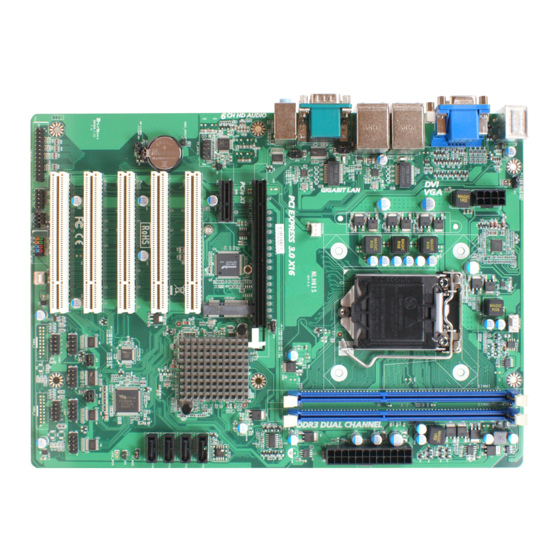
Page 6: Layout Diagram
1-2 Layout Diagram Rear IO Diagram Serial Port RJ-45LAN Ports (COM3) VGA Port Line-IN PS/2 Mouse Port Line-OUT PS/2 MIC-IN Keyboard Port Serial Port DVI-D Port USB2.0 Ports (COM1) Internal Diagram: ATX 12V Power Connector PS/2 Mouse Port over PS/2 Keyboard Port CPUFAN Header DDRIII DIMM Slot*2 VGA Port over... - Page 7 Motherboard Jumper Position JBAT Jumper Jumper Name Description JBAT CMOS RAM Clear Function Setting 3-Pin Block (2.54 pitch) KB/MS Power on Function Setting 3-pin Block (2.54 pitch) COM1 Port Pin9 Function Select 4-pin Block (2.54 pitch) COM3 Port Pin9 Function Select 4-pin Block (2.54 pitch) Mini PCI-E Slot VCC3.3V/3.3VSB Select...
- Page 8 Connectors Connector Name ATXPWR1 ATX Power Connector ATX12V1 ATX 12V Power Connector SATAII Connector SATA1 SATA2/3/4 SATAII Connector X3 Video Graphic Attach Connector DVI-D Port Connector COM1 RS232 Serial Port Connector COM3 RS232/422/485 Serial Port Connector UL1(Top)/UL2(Top) RJ-45 LAN Connector X2 UL1(Middle &...
-
Page 9: Chapter 2 Hardware Installation
Chapter 2 Hardware Installation 2-1 Jumper Setting JBAT (3-pin): Clear CMOS Function Settings (2.54 pitch) JBAT JP1 (3-pin): KB/MS Power on Function Setting (2.54 pitch) 1-2 Closed: KB/MS Power on Function Disabled (default) 2-3 Closed: KB/MS Power on Function Enabled JP2 (4-pin): COM1 Port Pin9 Function Select (2.54 pitch) - Page 10 JP3 (4-pin): COM3 Port Pin9 Function Select (2.54 pitch) JP4 (3-pin): Mini PCI-E Slot VCC 3.3V/3.3 VSB Select (2.54 pitch) JP6 (4-pin): COM2 Header Pin9 Function Select (2.54 pitch) 2-4 Closed: 3-4 Closed: 4-6 Closed: RI=RS232 RI=5V RI=12V.
-
Page 11: Connectors And Headers
JP7 (4-pin): COM4 Header Pin9 Function Select (2.54 pitch) Connectors and Headers 2-2-1 Rear I/O Back Panel Connectors Serial Port (COM3) RJ-45 LAN Ports VGA Port Line-IN PS/2 Mouse Port Line-OUT PS/2 MIC-IN Keyboard Port Serial Port DVI-D Port USB2.0 Ports (COM1) (1) PS/2 Mouse &... -
Page 12: Motherboard Internal Connectors
(6) Serial port Connector: COM3 /COM1 COM1 (9-pin Block): RS232 Port; COM3 (9-pin Block): RS232/422/485 Port COM1 port can function as RS232 port. COM3 port can function as RS232/422/485 port. In normal settings COM3 functions as RS232 port. With compatible COM cable COM3 can function as RS422 or RS 485 port. - Page 13 ** We recommend that you use an ATX 12V Specification 2.0-compliant power supply unit (PSU) with a minimum of 350W power rating. This type has 24-pin and 4- pin power plugs. ** If you intend to use a PSU with 20-pin and 4-pin power plugs, make sure that the 20-pin power plug can provide at least 15A on +12V and the power supply unit has a minimum power rating of 350W.
- Page 14 (2) ATX12V (8-pin block): 12V Power Connector This is a new defined 8-pin connector that usually comes with ATX Power Supply that supports extra 12V voltage to maintain system power consumption. Without this connector might cause system unstable because the power supply can not provide sufficient current for system.
-
Page 15: Header Pin Definition
2-2-3 Header Pin Definition (1) FP_AUDIO (9-pin): Line-Out, MIC-In Header (2.54 pitch) This header is connected to Front Panel Line-out, MIC connector with cable. FP_AUDIO Pin1 (2) HDMI_SPDIF (2-pin): HDMI-SPDIF Out header (2.54 pitch) HDMI_SPDIF (3) GPIO_CON (10-pin): GPIO Header (2.54 pitch) GPIO_CON... - Page 16 (4) PARALLEL (25-pin): Parallel Port Header (2.54 pitch) Pin14 Pin1 Parallel Port Header PARALLEL Pin NO. Pin Definition Pin NO. Pin Definition Pin 1 STB- Pin 14 AFD- Pin 2 PRD0 Pin 15 ERR- Pin 3 PRD1 Pin 16 INIT- Pin 4 PRD2 Pin 17...
- Page 17 (5) JW-FP (9-pin): Front Panel Header (2.54 pitch) JW_FP (6) PWRLED1 (3-pin): PWR LED Header (2.54 pitch) Pin1 PWRLED1 (7) SPEAK1 (4-pin): Speaker Header (2.54 pitch) SPEAK1...
- Page 18 (8) USB 2.0 Port Headers (9-pin): USB2/USB3 (2.54 pitch) USB2 USB3 (9) COM2/4/6/5: Serial Port Header (2.54 pitch) COM4:RS232/422/485 serial port header; COM2/6/5: RS232 serial port header only. Pin6 Pin1 COM2 *RS422 *RS485 Pin NO. RS232 (COM4 only) (COM4 only) DATA- Pin 1 Pin 2...
- Page 19 (10) CPUFAN1 (4-pin): CPUFAN Header (2.54 pitch) CPUFAN1 (11) SYSFAN1/SYSFAN2 (3-pin): SYSFAN Headers (2.54 pitch) SYSFAN1 SYSFAN2...
-
Page 20: Chapter 3 Introducing Bios
Chapter 3 Introducing BIOS Notice! The BIOS options in this manual are for reference only. Different configurations may lead to difference in BIOS screen and BIOS screens in manuals are usually the first BIOS version when the board is released and may be different from your purchased motherboard. -
Page 21: Bios Menu Screen
BIOS Menu Screen The following diagram show a general BIOS menu screen: Menu Bar General Help Items Current Setting Value Menu Items Function Keys BIOS Menu Screen Function Key In the above BIOS Setup main menu of, you can see several options. We will explain these options step by step in the following pages of this chapter, but let us first see a short description of the function keys you may use here: ... -
Page 22: Menu Bars
3-5 Menu Bar There are six menu bars on top of BIOS screen: Main To change system basic configuration Advanced To change system advanced configuration Chipset To change chipset configuration Boot To change boot settings Security Password settings Save & Exit Save setting, loading and exit options. -
Page 23: Advanced Menu
3-7 Advanced Menu NLH61S-6C Series ERP Support Use this item to select Energy-Related Products function. Disable ERP to active all wake-up functions. This optional settings are: [Disabled]; [Auto]. Launch PXE OpROM policy This option controls the execution of UEFI and Legacy PXE OpROM. The optional settings are: [Do not launch];... - Page 24 Extended Tag The optional settings: [Disabled]; [Enabled]. When set as [Enabled] it will allow device to use 8-bit tag field as a requester. No Snoop Use this item to enable or disable PCI Express device No Snoop option. The optional settings are: [Disabled]; [Enabled]. Maximum Payload Use this item to set maximum payload of PCI Express device or allow system BIOS to select the value.
- Page 25 The optional settings are: [Disabled]; [Enabled]. When set as [Enabled], the downstream port disables its traditional device number field being 0 enforcement when turning a Type 1 Configuration Request into a Type 0 Configuration Request, permitting access to extended functions in an ARI device immediately below the port. The default value is disabled.
- Page 26 If supported by hardware and set to [Disabled], this will disable the hardware’s ability to change link speed except speed rate reduction for the purpose of correcting unstable link operation. ACPI Settings Press [Enter] to make settings for system SCPI parameters. ACPI Settings: ACPI Sleep State Use this item to select the highest ACPI sleep state the system will enter when the suspend button...
- Page 27 When set as [Enabled], a VHM can utilize the additional hardware capabilities provided by Vanderpool Technology. Hardware Prefetcher Use this item to turn on/off the Mid Level Cache (L2) streamer prefetcher. The optional settings: [Enabled]; [Disabled]. Adjacent Cache Line Prefetch Use this item to turn on/off prefetching of adjacent cache lines.
- Page 28 USB Transfer time-out Use this item to set the time-out value for control, bulk, and interrupt transfers. The optional settings are: [1 sec]; [5 sec]; [10 sec]; [20 sec]. Device reset time-out Use this item to set USB mass storage device start unit command time-out. The optional settings are: [10 sec];...
- Page 29 Use this item to enable or disable serial port. The optional settings are: [Disabled]; [Enabled]. When set as [Enabled], users can make more settings for the following sub-items: Change Settings Use this item to select an optimal setting for super IO device. The optional settings are: [Auto];...
-
Page 30: Chipset Menu
temperature. CPUFAN Full-Speed Duty Use this item to set CPUFAN full speed duty. Fan will run at full speed when above the pre-set duty. CPUFAN Idle-Speed Temperature Use this item to set CPUFAN idle speed temperature. Fan will run at idle speed when below this temperature. - Page 31 The optional settings are: [Enabled]; [Disabled]. USB Port Pre-Port Disable Control Use this item to control each of the USB ports (0~13) disabling. When set as [Enabled], users can enable or disable ‘USB Port #0 Disable~ USB Port #13 Disable’. Azalia HD Audio Use this item to control detection of the azalea device.
- Page 32 Aperture Size Use this item to select the Aperture Size. The optional settings are: [128MB]; [256MB]; [512MB]. DVMT Pre-Allocated Use this item to select DVMT 5.0 pre-allocated (fixed) graphics memory size used by the internal graphics device. The optional settings are: [32M]; [64M]; [96M]; [128M]; [160M]; [192M]; [224M]; [256M]; [288M]; [320M];...
- Page 33 Custom Profile Control Press [Enter] to make settings for the following sub-items: Memory Frequency Limiter Use this item to set maximum memory frequency selection in Mhz. The optional settings are: [1067]; [1333]; [1600]. Use this item to set cas latency range 4-18. tRCD Use this item to row to col delay range 1-38.
-
Page 34: Boot Menu
3-9 Boot Menu Boot Configuration: Setup Prompt Timeout Use this item to set number of seconds to wait for setup activation key. Bootup Numlock State Use this item to select keyboard numlock state. The optional settings are: [On]; [Off]. Quiet Boot Use this item to enable or disable quiet boot option. -
Page 35: Security Menu
3-10 Security Menu Security menu allow users to change administrator password and user password settings. Administrator Password This item allows user to set administrator password. User Password This item allows user to set user password. 3-11 Save & Exit Menu Save Changes and Reset This item allows user to reset the system after saving the changes. - Page 36 Save as User Defaults Use this item to save the changes done so far as user defaults. Restore User Defaults Use this item to restore defaults to all the setup options. Launch EFI Shell from filesystem device This item is used for attempts to launch EFI shell application from one of the available file system devices.
Need help?
Do you have a question about the JNLH61S-6C Series and is the answer not in the manual?
Questions and answers