Advertisement
Quick Links
Advertisement

Related Manuals for JETWAY FDF05


Summary of Contents for JETWAY FDF05
- Page 1 Quick Installation Manual NO. G03-FDF05QIG-F Manual Revision: 1.0 Release Date: Sep 14, 2021...
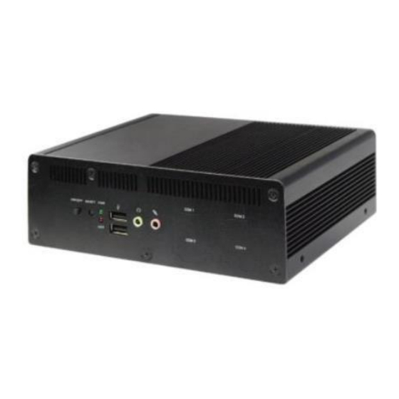
- Page 2 I/O Outlets...
- Page 3 Dimension and Outlines I. To Dissemble the Chassis 1. Locate the screws at the spots marked on this side of the system and unscrew them one by one.
- Page 4 2. Remove the marked screw on the front IO panel. 3. Remove the marked screw on the rear IO panel. 4. Lift the cover up to open the chassis. 5. The overview of the internal structure of the system.
- Page 5 II. To Install SO-DIMM to the board 1. Locate the SO-DIMM slot on the board. 2. Insert the gold-figure side of the compatible SO-DIMM into the slot at a 30 degree angle. See to it that the break of the module fit into the notch of the slot and the golden-finger side should be fully plugged into the slot.
- Page 6 3. Press down to secure the SO-DIMM to the slot. The eject tabs will lock automatically if installing direction is correct. III. To Install M.2 M-Key (2242/2280) PCIe Card 1. Locate the M.2 M-Key PCIe (2242/2280) slot on the board. Prepare compatible M.2 M-Key PCIe (2242/2280) card.
- Page 7 2. To install compatible card, please remove the screw in the marked spot at first. 3. Insert compatible M.2 PCIe (2280) card into the slot. See to it that the golden-finger side should be fully plugged into the slot.
- Page 8 4. Tighten up the screw removed before to the marked spot to secure the card. Note: The screw post and nut fixed at location MH4 by default for 8cm type-2280 card installation. If you wish to install type-2242 card, please remove corresponding screw post under the screw as well and lock the screw post into location MH2 before installing 4.2 cm card to the slot.
- Page 9 2. Remove the marked screw and use it to lock compatible card to the slot in later installation. 3. Insert the gold-figure side of the compatible card into the slot and press down. See to it that the golden-finger side should be fully plugged into the slot.
- Page 10 4. Secure the card to the board by tightening up the screw to the marked spot. 5. Locate the reserved antenna holes on the rear panel. Remove the dust-proof plugs on the marked spots from the panel to install the antenna. 6.
- Page 11 The washer ① & the hexagonal screw nut ②. Push the washer ① through the antenna head. 7. And then lock the antenna screw head to the front side of the rear panel with the hexagonal screw nut② and tighten it up. 8.
- Page 12 9. Repeat step 6 to 8, to finish installation of the other antenna. Notice: When all necessary installations are finished, please make sure that all cables unplugged before installations are connected to their original locations before restoring the back cover to the chassis and screws on the front panel/back panel/top cover locked to its original locations (Refer to Part I).
- Page 13 3. Wall mount the system by tightening 4 screws in the marked positions on both sides of the wall racks. Note: The 3 smaller holes on both sides of the rack are reserved for DIN rail installation. See to it that the three smaller screw holes on one installed rack should be parallel to those on the other rack;...
Need help?
Do you have a question about the FDF05 and is the answer not in the manual?
Questions and answers