
Subscribe to Our Youtube Channel
Related Manuals for Marshall Amplification V-R171X-DLW


Summary of Contents for Marshall Amplification V-R171X-DLW
-
Page 1: Operating Instructions
Marshall Electronics V-R171X-DLW Model No. 17" Full Resolution Dual Link / Waveform Monitor Operating Instructions... - Page 2 This page intentionally left blank...
-
Page 3: Table Of Contents
Power Input...7 VESA 75mm and 200 mmHole Pattern ...7 Power Input...7 DVI-I Input Connector ...7 Compatible Input Formats ... 8 DLW Monitor Layouts ... 9 On-Screen Menu... 11 STRUCTURE OVERVIEW ...11 MAIN MENU AND NAVIGATION...12 Marker Setup Submenu...12 16:9 Markers ...13 4:3 Markers ...13... -
Page 4: Features
Color temperature adjustment, aspect ratio settings, blue-only mode, and monochrome mode are a few of the advanced features allowing the V-R171X-DLW to be at home in any broadcast environment. Pixel-to-Pixel mode also allows native display of any incoming image format. -
Page 5: Installation And Initial Setup
Connect the required cables for video signals input and output. (Power must be applied to the V-R171X-DLW for the active loop-though output to be activated.) The monitor defaults to ‘ON’ when power is supplied. -
Page 6: Front Panel Features
Front Panel Features Power Button Turn the monitor off or on by pressing the power button. The LED on the power button is at maximum illumination when the unit is OFF. The LED is at minimum illumination when the unit is on. -
Page 7: Rear Panel Features
Rear Panel Features RS-422/485 Serial Interface The RS-422/485 ports are used to remotely control the IMD or all V-R171X-DLW features, using a variety of industry standard protocols. (Note: Connector/pin-out may need to be adapted depending on protocol and controlling device used.) Only one connection to either port is needed... -
Page 8: Compatible Input Formats
Compatible Input Formats The following SDI standards are supported by the V-R171-DLW: 525i, 625i 720p (60, 59.94, 50) 720p (30 / 29.97) 1035i (60 / 59.94) 1080i (60 / 59.94 / 50) 1080psF (24 / 23.98) 1080p (30 / 29.97 / 25 / 24 / 23.98) The following 3G-SDI standards are supported by the V-R171-DLW 1080p (60 / 59.94 / 50) YCbCr –... -
Page 9: Dlw Monitor Layouts
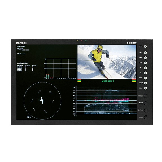
DLW Monitor Layouts The V-R171X-DLW has 4 possible layouts, Multi mode, Vectorscope mode, Waveform mode and Full Screen Video mode. Each press of the LAYOUT Button will change the current mode to next available mode. Default Multi mode Layout Vectorscope Mode... - Page 10 Waveform Monitor Mode Full Screen Video Mode...
-
Page 11: On-Screen Menu
On-Screen Menu STRUCTURE OVERVIEW... -
Page 12: Main Menu And Navigation
MAIN MENU AND NAVIGATION Access and navigate the main menu using the RotoMenu™ knob: Using the RotoMenu knob • Press the RotoMenu™ knob to enter the main menu. • Rotate the knob to scroll up or down in the main menu or each submenu. •... -
Page 13: 16:9 Markers
■ 16:9 Markers Use this setting to superimpose one of 10 markers on the screen when in 16:9 or Full Screen mode. This setting is disabled when the aspect ratio is set to 4:3, or when Pixel-to-Pixel mode is enabled. Note that in Full Screen mode, markers are vertically stretched along with the picture to fit the 16:10 screen. -
Page 14: Marker Background
■ Marker Background Use this setting to choose how selected markers are displayed on the screen: • Off The marker is superimposed on the complete image. • 50% Gray Screen area beyond the marker is shown at 50% intensity. • Black Screen area beyond the marker is shown as black. -
Page 15: Monochrome Mode
■ Aspect Ratio Settings Use this menu option to switch between several aspect ratio settings. As the V-R171X-DLW monitor has a native resolution of 1920x1200 RGB pixels, incoming images are automatically scaled to fit the screen: • In 4:3 mode, images are scaled up or down to fill the maximum 4:3 portion of the screen (1600 x 1200). IMD text and time code are superimposed on the lower portion of the image. -
Page 16: Curtain Color
10%. The diagrams on the following show how IMD text, timecode, and the audio monitor icon are simultaneously displayed on the screen in each aspect ratio setting. The white area represents the video image. -
Page 17: Dvi-D Csc Mode
The HDMI CSC Auto setting is used to accommodate newer HDMI interfaces that send colorspace signaling in the HDMI data stream. If this setting is set to On, the monitor will automatically determine which colorspace setting to use. If this setting is set to Off, or your HDMI signal does not contain colorspace signaling, the DVI-D CSC Mode described above will determine the colorspace configuration. -
Page 18: User-Definable Function Buttons
MFG. (Factory defaults cannot be overwritten.) • Use To perform a full system restore, which resets ALL adjustable fields on the monitor to their “fresh-from- factory” state, press the Power, F1 and F2 button simultaneously. Note: You will lose ALL user adjustable settings on your monitor. -
Page 19: Osd Config Submenu
Use this setting to enable or disable status display. When enabled, the current video input standard is displayed on the top left of the screen. When disabled, status is only displayed for 2 seconds when the monitor is powered on, when an input is applied, or when the input video standard changes. -
Page 20: Osd Tally
Red, yellow, and green tally is displayed according the protocol commands. Green, red, and yellow colors are shown individually on either the bottom left or right of the screen. ■ LED Tally Use this to enable or disable the physical LED tally on the top of the monitor. Anc. Timecode ■ 00:00:00:... -
Page 21: Audio Monitor
■ Audio Monitor Use the Audio Monitor menu option to enable or disable the audio presence indicator icon. When enabled, this icon indicates whether embedded audio is present in the HD/SDI video input. A red circle and cross will flash on the icon if no embedded audio is present. -
Page 22: Imd Config Submenu
IMD Config Submenu ■ Overview The V-R171X-DLW features an In-Monitor Display (IMD) with the ability to display on-screen text and tally in three colors. IMD text, color, and alignment can be assigned to each screen locally using menu options (see below). -
Page 23: Tally Source
This protocol setting accepts Image Video commands via MEI protocol, for use when an Image Video controller is connected to the Marshall Network Controller box. ■ Tally Source The V-R171X-DLW OSD tally can be controlled in a variety of different ways. Use the Tally Source setting to choose how tally is controlled: Standard Use the Standard setting to control tally via contact closure on the HD-15 tally interface. -
Page 24: Imd Tally Mode
Press RotoMenu™ knob to edit the IMD Name. Rotate the RotoMenu™ knob to move the cursor. Press the RotoMenu™ knob with the cursor on the character to be changed, then rotate the knob to scroll through the character set . Press the RotoMenu™ knob to choose a character. ■... -
Page 25: Closed Captioning Submenu
708 (608 Comp.). Use this section to choose which type of stream you would like to decode. ■ 608 Service The EIA-608 caption protocol defines four channels of caption information. The V-R171X-DLW monitor can only display one of these four channels at any point in time. With the 608 Service selection, you can select which of the four streams to render on the screen. -
Page 26: Wave/Vector Submenu
Use the Wave/Vector submenu to change the location of the Waveform Monitor and Vectorscope, as well as the data displayed on the Waveform monitor or the Vectorscope on the V-R171X-DLW monitor. The Waveform Monitor can also be customized to conform to different scales, to display different colors, differentiate data with Limits. The Vectorscope targets can also be changed in this menu. - Page 27 All Waveform display data within the limits will appear in white. ■ Limit Max Use this to set the desired maximum for the Limit display of the waveform monitor. Any Waveform data that goes beyond this Limit Max will be displayed in red.
-
Page 28: Ancillary Submenu
DLW monitor display. ■ DID/SDID Use this section to select which packet IDs should be counted on the DLW monitor display. For example, 0x6060 would count the Timecode data packets, 0x6101 would count the EIA-708 CC data packets and 0x6102 would count... -
Page 29: Service Submenu
SERVICE SUBMENU ■ Software Version Display The Main Board, Keypad, and FPGA software version numbers are displayed. The following information is displayed: • rel: • ipa • dlw • ipap • kp Service Menu Release Package version number Input processor firmware FPGA Version Product Type Keypad version number... -
Page 30: Specifications
Specifications ■ PANEL Screen Size 17” Diagonal Display Area (h x v) 367.20 x 229.50 mm Aspect Ratio 16:10 Native (4:3/16:9 Modes) Pixels 1920 x RGB x 1200 Color Depth 8-bit Viewing Angle (h x v) 140° x 120° Brightness 400 cd/m Contrast Ratio 600:1... -
Page 31: Maintenance
This warranty is extended to the first consumer only, and proof of purchase is necessary to honor the warranty. If there is no proof of purchase provided with a warranty claim, Marshall Electronics reserves the right not to honor the warranty set forth above. - Page 32 Burn-In Warning This monitor uses a high quality TFT LCD panel. However, if a static image is left on the screen for 48 hours, there may be a 30 second to 10 minute recovery period for the panel. During recovery, a very faint image may be retained on the...
- Page 33 Marshall Electronics, Inc. 1910 East Maple Ave. El Segundo, CA 90245 Tel: (800) 800-6608 / (310) 333-0606 • Fax: 310-333-0688 www.LCDRacks.com • sales@lcdracks.com 2010-1217...
Need help?
Do you have a question about the V-R171X-DLW and is the answer not in the manual?
Questions and answers