Table of Contents
Advertisement
Quick Links
Advertisement
Table of Contents

Related Manuals for JRC JHS-182


Summary of Contents for JRC JHS-182
- Page 1 Automatic Identification System JHS-182 Instruction Manual 7ZPJD0226...
- Page 2 Preface Thank you for purchasing JHS-182 Automatic Identification System (AIS). JHS-182 is the Class A shipborne AIS equipment that communicates the ship’s static data and the ship’s dynamic data with ships or coast stations on VHF channels using TDMA techniques.
- Page 3 Before Operation Concerning the symbols This manual uses the following symbols to explain correct operation and to prevent injury or damage to property. The symbols and descriptions are as follows. Understand them before proceeding with this manual. WARNING Indicates a warning that, if ignored, may result in serious injury or even death.
- Page 4 Handling Precautions WARNING Do not disassemble or customize this unit. Doing so may cause fire, electrical shock or malfunction. Do not use a voltage other than specified. Doing so may cause fire, electrical shock or malfunction. Do not attempt to service the interior of this equipment with the exception of qualified service personnel, as doing so may cause fire, electric shock or malfunction.
- Page 5 Handling Precautions CAUTION Do not use this equipment for anything other than specified. Doing so may cause malfunction or damage to persons. Do not adjust the trimmer resistors or the trimmer capacitors on the PCB unit, except when and if they need to be adjusted. Doing so may cause malfunction or damage to persons.
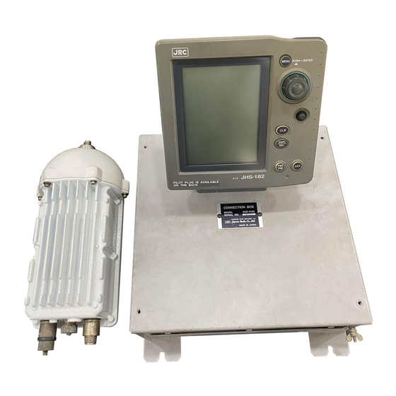
- Page 6 External Views NTE-182 AIS Transponder NCM-779 AIS Controller...
- Page 7 NQE-3182 Connection Box...
- Page 8 NBD-577B Power Supply Unit NQD-4382 Junction Box...
-
Page 9: Table Of Contents
CONTENTS 1.GENERAL ...................... 1-1 1.1 Outlines ....................... 1-1 1.2 Features ...................... 1-1 1.3 Components ....................1-2 1.3.1 Standard Components ................1-2 1.3.2 Options ....................1-2 1.3.3 Configuration .................... 1-3 1.4 Outline ......................1-4 2.INSTALLATION DIAGRAM ................2-1 3.PART NAMES AND FUNCTIONS ..............3-1 4.DISPLAYS ...................... - Page 10 7.AFTER-SALES SERVICE ................7-1 Before returning repair ..................7-1 Periodical maintenance recommended ............7-1 8.SPECIFICATIONS ..................8-1 8.1 General (JHS-182) ..................8-1 8.2 AIS TRANSPONDER (NTE-182) ..............8-1 8.3 AIS CONTROLLER (NCM-779) ..............8-1 8.3.1 Operation panel ..................8-1 8.3.2 Environmental condition ................8-1 8.3.3 External interfaces ..................
-
Page 11: General
● Increased Probability of Vessel Detection ━━━━━━━━━━━━━━━━━━━━━━━━━━━━━━━━━━━━━━━━━━━ JHS-182 is equipped with a guard zone alert function. When preset guard zone range and other vessel enters into the zone, JHS-182 indicates and sounds the alert. This function enhances probability of vessel detection. -
Page 12: Components
Components 1. 3. 1 Standard Components Name Type Quantity Remarks AIS Transponder NTE-182 With whip antenna Connection box NQE-3182 AIS Controller NCM-779 With Pilot Plug Control cable 7ZCJD0214A L=10m Spare parts 7ZXJD0049 Fuses Instruction manual 7ZPJD0226 1. 3. 2 Options Options Type Quantity Remarks... -
Page 13: Configuration
1. 3. 3 Configuration • System Block Diagram... -
Page 14: Outline
Outline • Outline Drawing of NTE-182 AIS Transponder ━━━━━━━━━━━━━━━━━━━━━━━━━━━━━━━━━━━━━━━━━━━ Unit: mm Mass: approx. 2.6 kg... - Page 15 • Outline Drawing of NCM-779 AIS Controller ━━━━━━━━━━━━━━━━━━━━━━━━━━━━━━━━━━━━━━━━━━━ Unit: mm Mass: approx. 1.0 kg...
- Page 16 • Outline Drawing of NQE-3182 Connection Box ━━━━━━━━━━━━━━━━━━━━━━━━━━━━━━━━━━━━━━━━━━━ Unit: mm Mass: approx. 2.5 kg...
- Page 17 • Outline Drawing of NBD-577B Power Supply Unit ━━━━━━━━━━━━━━━━━━━━━━━━━━━━━━━━━━━━━━━━━━━ Unit: mm Mass: approx. 3.8 kg...
-
Page 18: Installation Diagram
2. INSTALLATION DIAGRAM Notes: Leave installation of this equipment to our service center or agents. Installation by an unauthorized person may results in malfunction. -
Page 19: Part Names And Functions
3. PART NAMES AND FUNCTIONS NCM-779 AIS controller ② ... - Page 20 ⑨ ⑫ ...
-
Page 21: Displays
4. DISPLAYS Display Title Current Time MAIN MENU UTC 11:43 BRG : RNG NAME / MMSI 270°: 0.18NM OCEAN-LINE List of Other Ships 35°: 0.29NM QUEEN Displays three ships at * 22°: 0.92NM ABCDEFG−MARU the minimum always. Main display Displays other ships list, Graphic Display, Menu for operation, Other ship’s and own ship’s detail information G U A R D ... -
Page 22: Operation
5. OPERATION 5.1 Menu Tree *( ) is not displayed depending on the selection. Other Ships List Setting LIST SORT NAME JOG DIAL OWN POS DISP OWN DETAIL Own Ship's Detail (PGUP) (PGDN) JOG DIAL (Power On) Jog Dial or Stick Other Ship's detail Information Other Ships List Jog Dial or Stick... -
Page 23: Basic Operation
5.2 Basic Operation 5.2.1 Turning ON the power Holding down the PWR/DIM key for one second turns on the power, the starting screen appears about 5 seconds later, and then the Other Ships List display appears about 40 seconds later. Check the main power supply of a switchboard, the switch in the NQE-3182 Warning: ... - Page 24 To scroll the selected ship’s name that is more than 11 letters, press the Joy Stick to the right or the left.(See the following figure and PAGE SCROLL 5.2.1.4) SORT:NORTH/RANGE UTC11:43 Press the Joy Stick to SORT:NORTH/RANGE UTC11:43 the right. BRG : RNG NAME / MMSI BRG : RNG ...
-
Page 25: Other Ship's Detail Information
5.2.1.2 Other Ship’s Detail Information The Other Ship’s Detail Information is displayed if the Jog Dial or Joy Stick is pressed when the other ship is selected on the Other Ships List or the Graphic Display. SHIPʼS DETAIL UTC11:46 ... -
Page 26: Own Ship's Detail Information
5.2.1.3 Own Ship’s Detail Information The Own Ship’s Detail Information is displayed when own ship is selected in the Other Ships List display or the Graphic display. Also, selecting [OWN DETAIL] in the setup of the Other Ships List displays the Own Ship’s Detail Information. -
Page 27: Display Setup Of Other Ships List
5.2.1.4 Display Setup of Other Ships List The Other Ships List can display a maximum of 16 ships (14 ships when the Own Position Display is displayed) at one time. And the ships can be displayed by doing a following order figure if there are more ships. ... - Page 28 b) Display setup of the Own Position Display It can be set to display or not the own ship’s position with the Other Ships List. To set the own ship’s position display, select [OWN POS DISP] in the small window of the Other Ships List. ...
- Page 29 c) Page Scroll • ‘▼’ mark is displayed on the bottom line and [PGDN] is displayed in the small window when the Other Ships List is able to scroll downward. • ‘▲’ mark is displayed on the top line and [PGUP] is displayed in the small window when the Other Ships List is able to scroll upward.
-
Page 30: Graphic Display
5.2.1.5 Graphic Display Pressing [DSPL/SEL] key switches alternately between text and graphic display. (See 5.4 Graphic Display Function) SORT:NORTH/RANGE UTC11:43 SORT:NORTH/RANGE UTC11:44 BRG : RNG NAME / MMSI BRG : RNG NAME / MMSI 180°: 0.18NM |OCEAN-LINE 180°: 0.18NM|OCEAN-LINE 55°: 0.21NM QUEEN 35°: 0.21NM QUEEN * 0°: 0.30NM ABCDEFG-HIJK> * 22°: 0.30NM ABCDEFG-MARU ... -
Page 31: Turning Off The Power
5.2.2 Turning OFF the power WARNING: The PASSWORD must be entered to turn off the power. The password preset before shipment is “0000”. The administrator must manage PASSWORD. Press OFF key for turning off the power at first. The Display of PASSWORD Input (refer to the following figure) is displayed after pressing OFF key. -
Page 32: Alarm
5.2.3 Alarm 5.2.3.1 Guard Zone Alarm When a ship enters within the guard zone range, the alarm status “GUARD” appears on the display and an alarm buzzer beeps. Refer to “5.3.3 Setting Alarm. The ship within the guard zone range is displayed in reverse. SORT:NORTH/RANGE UTC11:43 ... -
Page 33: Keyboard Display And Input Method
5.2.4 Keyboard Display And Input Method MAIN MENU UTC 11:43 BRG : RNG NAME / MMSI When input operation starts, the cursor is on “A” in the keyboard 270°: 0.18NM OCEAN-LINE area at the bottom left of the screen. 35°: 0.29NM QUEEN * 22°: 0.92NM ABCDEFG−MARU The cursor jumps into the Text Setting Window if the Jog Dial is ... -
Page 34: Main Menu
5.3 MAIN MENU Main Menu displays menu items for setting, sending messages, and maintenance, etc.. To display the Main Menu, press the MENU key during operation. MAIN MENU UTC11:44 BRG : RNG NAME / MMSI 270°: 0.18NM OCEAN-LINE 35°: 0.29NM QUEEN * 22°: 0.92NM ABCDEFG-MARU 1.VOYAGE STATIC DATA 2.MESSAGE 3.ALARM SETTING ... -
Page 35: Voyage Data Setting
5.3.1 VOYAGE DATA SETTING When 1. VOYAGE STATIC DATA is selected, a menu for setting voyage data appears When the Jog Dial is rotated, the cursor moves upwards or VOYAGE DATA SET UTC11:44 downwards accordingly. BRN : RNG NAME / MMSI 270°: 0.18NM OCEAN-LINE Select an item from the menu. 35°: 0.29NM ... -
Page 36: Navigational Status
5.3.1.1 NAVIGATIONAL STATUS When 1.NAVIGATIONAL STATUS is selected, the navigational status is ready to be selected. When the Jog Dial is pressed on 1.NAVIGATIONAL STATUS, the cursor is moved down to the second line. On the line, the displayed item changes as the Jog Dial is rotated. Therefore rotate the Jog Dial until the item to select is displayed. -
Page 37: Destinations Entry
5.3.1.2 Destinations Entry When 2.DESTINATION is selected, the name of the destination is ready to be entered. The name can be entered with the keyboard on the bottom left of the screen. See“5.2.4 KEYBOARD DISPLAY AND INPUT METHOD” for the operation of the keyboard. VOYAGE DATA SET UTC11:44 ... -
Page 38: Draught Value Entry
5.3.1.4 Draught Value Entry When 4. DRAUGHT in the Voyage Data Setting Menu (5.3.1) is selected, the draught value is ready to be entered. Enter the value according to the procedure of ”5.2.5 Numerical Input.”. Up to 25.4 or “25.5 or more” can be entered as the draught value. ... -
Page 39: Cargo Type Selection
5.3.1.5 Cargo Type Selection When 5.CARGO/STATUS is selected, Cargo Type is ready to be selected. When 5.CARGO/STATUS is selected, the cursor moves to the second line. Rotate the Jog Dial until the menu item to select. If the Jog Dial is pressed, the selection is made and the cursor moves to the next item (6. Waypoint) ... -
Page 40: Waypoints Setting
5.3.1.6 Waypoints Settings When 6. WAYPOINTS is selected, the Waypoints Setting appears. Up to 14 Waypoints can be set WAYPOINTS UTC11:44 Rotate the Jog Dial to move the cursor for selecting the number of BRG : RNG NAME / MMSI the waypoints. 270°: 0.18NM OCEAN-LINE 35°: 0.29NM QUEEN ... - Page 41 a) Waypoint Setting Procedure SETTINGS WAYPOINTS ITEMS WAYPOINTS UTC11:44 WAYPOINTS UTC11:44 BRG : RNG NAME / MMSI BRG : RNG NAME / MMSI 270°: 0.18NM OCEAN-LINE 270°: 0.18NM OCEAN-LINE 35°: 0.29NM QUEEN 35°: 0.29NM QUEEN * 22°: 0.92NM ABCDEFG−MARU * 22°: 0.92NM ABCDEFG−MARU NO. POSITION NO. POSITION 1. 89°59.999 1. N 89°59.999’ 179°59.999 E 179°59.999’ ...
- Page 42 Addition of Waypoints For adding new items between existing items, follow the procedure below: WAYPOINTS UTC11:44 If you want to add a setting between No.1 and No.2, then BRG : RNG NAME / MMSI put a cursor on No.1. 270°: 0.18NM OCEAN-LINE Press the Jog Dial one time for making blink.
-
Page 43: Waypoints Text Setting
Deletion of Waypoints For deleting existing waypoints, follow the deletion procedure below. But please do not use [ALL CLEAR] on the bottom of the screen for deleting Waypoints. WAYPOINTS UTC11:44 Move the cursor on the number of Waypoint item that you BRG : RNG ... -
Page 44: Persons On Board Entry
5.3.1.8 Persons On Board Entry When 8. PERSONS ON BOARD is selected, the number of persons on board can be entered. Enter the number with the Jog Dial. The persons on board can be set up to 8190 or “8191 or more”. Press the Jog Dial to confirm. -
Page 45: Re-Load Destination From Ever Set Data
5.3.1.10 Re-load destination from ever set data When the [DEST. LOAD] in the small window is selected, 5 entered destinations (the present destination and 4 destinations in the past) which can be displayed. ... -
Page 46: Message Menu
5.3.2 MESSAGE MENU When 2. MESSAGE is selected, MESSAGE MENU (a menu for sending/receiving messages) appears. Rotate the Jog Dial to move the cursor for selecting the item from MESSAGE UTC 11:44 menu. BRG : RNG NAME / MMSI Press the Jog Dial to confirm on the selected item. 270°: 0.18NM ... -
Page 47: Editing/Sending Messages
5.3.2.1 EDITING/SENDING MESSAGES When 1.EDIT AND TX is selected, the screens transit as the chart below shows. Message Menu Type of Message Text Editing Send & Save 】 Edit: After setting the Type of Message, edit it in “EDIT AND TX”display. Send: After editing the message, send and save the message, and then return to “MESSAGE MENU”. - Page 48 b) MESSAGE TYPE SETTINGS - setting example EDIT AND TX UTC11:44 From MESSAGE MENU (5.3.2), select 1. EDIT AND TX BRG : RNG NAME / MMSI and press the Jog Dial. 270°: 0.18NM OCEAN-LINE EDIT AND TX opens. When “EDIT AND TX” opens, the 35°: 0.29NM QUEEN cursor is on * 22°: 0.92NM ...
- Page 49 (5) CH (Channel) Select the transmitting channel: “AUTO”, “A”, “B” and “A/B” are selectable by rotating the Jog Dial. If the transmitting channel is selected automatically, select “AUTO”, use channel A then select “A”, use channel B then select “B”, and use channel A and B then select “A/B”. (6) NUMBER OF ENTRY “e) 5.3.2.2.
- Page 50 c) TEXT EDIT SCREEN Select [EDIT] on the bottom of the screen and display TEXT EDIT SCREEN for transmitting a text message. Enter texts, according to the procedure of “5.1.1 KEYBOARD DISPLAY AND INPUT METHOD”. EDIT AND TX UTC 11:44 TEXT EDIT SCREEN consists of three sub screens: BRG : RNG ...
- Page 51 d) SENDING AND SAVING MESSAGES In case, “FUNCTION” in Message Type Screen (see a), b) Message Type) is TEXT, for sending or saving messages, follow the instruction below: EDIT AND TX UTC 11:44 BRG : RNG NAME / MMSI 270°: 0.18NM OCEAN-LINE 1. Select [SAVE], and save the sent message. Then go to Message 35°: 0.29NM ...
-
Page 52: Tx Tray (Viewing Sent Messages)
5.3.2.2 TX TRAY (VIEWING SENT MESSAGES) TX TRAY menu is displayed when 2. TX TRAY is selected in the Message menu.. In the TX TRAY menu, transmitted messages can be display, or can be edited and transmitted again. TX TRAY UTC11:44 BRG : RNG NAME / MMSI ... -
Page 53: Rx Tray (Viewing Received Messages)
5.3.2.3 RX TRAY (VIEWING RECEIVED MESSAGES) RX TRAY menu is displayed when 3. RX TRAY is selected in the Message menu.. In the RX TRAY menu, received messages can be display, or can be edited and transmitted as reuse. ... -
Page 54: Interrogation
5.3.2.4 INTERROGATION INTEROGATION menu is displayed when 4. INTERROGATION is selected in the Message menu.. In the INTERROGATION menu, two destinations (DESTINETION 1 and DESTINETION 1) can be selected as interrogations simultaneously a) INTERROGATION SETTINGS INTERROGATION UTC11:44 BRG : RNG NAME / MMSI When the Jog Dial is rotated, the cursor moves between 270°: 0.18NM ... - Page 55 b) INTERROGATION REQUEST PATTERNS The possible patterns of interrogation are below: patterns of interrogations Request Request Request note Interrogation Class ...
- Page 56 c) ITEMS IN THE BOTTOM BOX In the Interrogation Screen (5.3.2.5), when one of the items in the bottom of the box, the system operates as mentioned below. [EXIT] ・・・・・・・・・・・・・・・・・・ Cancel the contents and return to Message Manu. [TX] ・・・・・・・・・・・・・・・・・・ Transmit to “DESTINATION1” (and ”DESTINATION2”) [CLEAR] ・・・・・・・・・・・・・・・・・・Cancel the contents and move the cursor on ”1.DESTINATION ID”...
- Page 57 d) VIEWING RESPONSED MESSAGES At Interrogation screen(5.3.2.5), when [CHECK○-○] ( [CHECK1-1], INTERROGATION UTC11:44 [1-2],or [2-1]) is selected, response messages are provided. BRG : RNG NAME / MMSI 270°: 0.18NM OCEAN-LINE 35°: 0.29NM QUEEN * 22°: 0.92NM ABCDEFG−MARU Pressing CLR key returns to the Interrogation Menu (5.3.2.5). MMSI : 123456789 NAV STATUS : MOORED ...
-
Page 58: Long Range Messages
5.3.2.5 LONG RANGE MESSAGES In Message Screen (5.3.2), if 5.LONG RANGE is selected, Long Rang Message Screen will be displayed. The set up of Long Range Message is mentioned in 5.3.4. (SET UP MENU). In SET UP MENU, select 4.LONG RANGE RESPONSE SETTING (5.3.4.4), and next select from AUTO or MANUAL. - Page 59 a) MANUAL RESPONSES For Long Range Message, when MANUAL RESPONCES is set, when the system receives Long Range Request, Long Range Screen is opened automatically Check the Response and REPLY manually to the message. 1.After Long Range Request, “Long Range Message ①”opens automatically. 2.When Other Ships reply, 『The other equipment replied』is displayed for 2 seconds.(③)...
-
Page 60: User Alarm Setting
5.3.3 USER ALARM SETTING ALARM SETTING menu is displayed when 3.ALARM SETTING is selected in the Main Menu. The alarms that users can change the alarm settings are GUARD ZONE ALARM and LOST TARGET ALARM. On this screen, users can change the settings of these alarms. Initially the cursor is on 1.GUARD ZONE. -
Page 61: Lost Terget Alarm Setting
5.3.3.2 LOST TERGET ALARM SETTING To set the Lost Target alarm, select in the USER ALARM SETTING menu. If the 2. LOST TERGET information of a other ship in the Lost Terget range for more than six minutes, a warning message-“LOST”... -
Page 62: Contrast Adjustment
5.3.4 SET UP MENU When 4. SETUP is selected from MAIN MENU, the menu for setting AIS Controller appears. SET UP UTC11:44 Setup of the AIS Controller functions and channel management of BRG : RNG NAME / MMSI the transponder. 270°: 0.18NM OCEAN-LINE 35°: 0.29NM QUEEN * 22°: 0.92NM ABCDEFG-MARU ... -
Page 63: Time Difference Setting
5.3.4.2 TIME DIFFERENCE SETTING Setup of local time, and select a display change of time. SET UP LMT13:22 BRG : RNG NAME / MMSI 270°: 0.18NM OCEAN-LINE 35°: 0.29NM QUEEN * 22°: 0.92NM ABCDEFG-MARU 1.CONTRAST : 49 2.TIME DIFFERENCE : ON (LOCAL TIME) :+09:00 LMT Rotate the Jog Dial and select the “2.TIME DIFFERENCE”. -
Page 64: Regional Channel Setting
5.3.4.3 REGIONAL CHANNEL SETTING When 3. REGIONAL CHANNEL SETTING is selected, Regional Channel Setting Menu appears. A maximum eight channel management information can be inputted. Rotate the jog dial to left/right and move the cursor for selecting the menu. Press the Jog Dial, then the sub menu displayed If CLR is pressed, the set up menu is displayed (5.3.4). ... - Page 65 [Explanation of the setting menus] CH A CH B 1. 2. are a menu for setting channel number and bandwidth. By rotating Jog Dial, input the channel number and confirm it by pressing the Dial. No. : Set up to the channels which are used. BANDWIDTH : Select the bandwidth from WIDE/NARROW TX/RX MODE : This menu is used for setting the transmission/receive (TX/RX) mode of CH A and CH B.
- Page 66 a) CONFIRMATION OF SETTINGS When you completed step 7 above, the cursor moves down to [EXIT] at the bottom of the screen. Bring the cursor on [CHECK] with the Jog Dial and press it. Then the result of diagnosis is displayed at the bottom of the screen.
- Page 67 When the [LOAD] in the small screen is selected in the Regional Channel Setting Menu, the preservation list of manual inputs is displayed. Moreover, the contents of the setting selected from preservation lists can be registered. Transponder saves a maximum of nine channel management information. The data applicable to the condition is eliminated when the ship is separated more than 500NM from the set-up area or when five weeks pass from the saved time.
- Page 68 The registered setup can be seen when the Jog Dial is rotated. Only the saved number of ・ data is displayed. ・ The CHANNEL SETTING display is displayed when the CLR key is pressed on the screen ① and ② states as the cursor is on the numbers. ・ ...
-
Page 69: Long Range Response Setting
5.3.4.4 LONG RANGE RESPONSE SETTINGS To set the Long Range Response, select 4.LONG RANGE RESPONSE Auto response (AUTO) and manual response (MANUAL) can be selected. This setting works when a long range communication device is connected. The default setting is AUTO. Use the Jog Dial for selection and confirmation. ... -
Page 70: Group Ship Registration
5.3.4.6 GROUP SHIP REGISTORATION When 6.GROUP SHIP is selected, GROUP SHIP opens. Use this screen for registering group ships. GROUP SHIP UTC11:44 Maximum 10 ships can be registered as a group ship. BRG : RNG NAME / MMSI When [SAVE] is selected, the information is saved. 270°: 0.18NM ... -
Page 71: Changing The Channel
5.3.4.7 CHANGING THE CHANNEL In case, a user want to change a channel, select 7.CHANNEL SETTING After that, type in password from Password Input Screen(①) and the proper password is entered, go to Next screen(②) ① ② ... -
Page 72: Changing Password
5.3.4.8 CHANGING PASSWORD Select PASSWORD, then the screen for Password setting appears. The passwords for turning off the electricity or changing channel are set up from this screen. A person who is in charge of ship should administrate passwords. PASSWORD UTC11:44 BRG : RNG ... -
Page 73: Changing Of Position Display Setting
5.3.4.9 Changing of Position Display Setting When the 9. POS DISP. SETTING is selected, the Position Display Setting (displaying position of N/S,E/W) can be changed. 10.POS DISP.SETTING: OFF Position Display Setting When the setting is ... -
Page 74: Maintenance
5.3.5 MAINTENANCE MAINTENANCE UTC11:44 When 5.MAINTENANCE selected from Main Menu (5.3) BRG : RNG NAME / MMSI Maintenance Menu appears. 270°: 0.18NM OCEAN-LINE 35°: 0.29NM QUEEN Users can check current status of the system by the menu. * 22°: 0.92NM ABCDEFG-MARU 1.SELF DIAGNOSIS 2.TRX CONDITION 3.ALARM HISTORY 4.SENSOR STATUS ... - Page 75 5.3.5.1. SELF DIAGNOSIS a) SELF DIAGNOSIS- OPERATIONS AND DISPLAYS SELF DIAGNOSIS UTC11:44 BRG : RNG NAME / MMSI 270°: 0.18NM OCEAN-LINE When 1.SELF DIAGNOSIS is selected from Maintenance Menu 35°: 0.29NM QUEEN (5.3.5), SELF DIAGNOSIS screen appears. * 22°: 0.92NM ABCDEFG-MARU 1.TRANSPONDER: TEST ALL Initially, the cursor is on 1.TRANSPONDER. And is the Jog Dial is : ENT ...
- Page 76 [About the contents of a display] The result and contents that accord to each diagnostic value are displayed as shown of the following figure. And the last diagnostic time is displayed. In addition,”--/-- --:--“ is displayed when time is not able to be acquired. Rotating the Jog Dial or moving the Joy Stick can display the next page.
- Page 77 5.3.5.2. TRX CONDITION When 2.TRX CONDITION is selected from Maintenance Menu (5.3.5), TRX CONDITION screen appears. This menu provides the information of how the setting has been changing. Eight records from the newest are displayed. 1. of this menu is TRX CONDITION UTC11:44 ...
- Page 78 5.3.5.3. ALARM HISTORY When 3.ALARM HISTORY is selected from Maintenance Menu (5.3.5), ALARM HISTORY screen appears. ALARM HISTORY UTC11:44 This screen displays a history of alarms which occur while the BRG : RNG NAME / MMSI power is on. It displays the alarm history from the most recent one 270°: 0.18NM ...
- Page 79 5.3.5.4. SENSOR STATUS When 4.SENSOR STATUS is selected from Maintenance Menu, SENSOR STATUS screen appears. The information of current status of sensor connection is displayed on this screen. Select [EXIT] at the bottom or press CLR key, and you can go back to Maintenance Menu. SENSOR STATUS UTC11:44 ...
- Page 80 5.3.5.5. POWER ON/OFF LOG When 5.POWER ON/OFF LOG is selected, maximum 20 lines of Power ON/OFF LOG is displayed. There is more than 20 lines of data, ▼▲ arrears at the bottom of the screen for indicating there are more information. You can scroll down/up the screen by clicking [SCROLL] when ▼ or ▲ exists on the screen.
-
Page 81: Software Version
5.3.5.6. SOFTWARE VERSION When 6.SOFTWARE VERSION is selected from Maintenance Menu, the version information of the software of each part are displayed. Select [EXIT] at the bottom or press CLR key, and you can go back to Maintenance Menu. ... -
Page 82: Graphic Display Function
5.4 Graphic Display Function 5.4.1 Operation keys for Graphic Display Function Graphic display on/off key NCM-779 Panel and Graphic Display 5.4.2 Operating Graphic Display Press [DSPL/SEL] key, then the display is alternated between text display and graphic display. -
Page 83: Operation
5.4.3 Operation 5.4.3.1 SETUP menu Pressing [CLR] key with selecting own ship moves the cursor to the SETUP window. Pressing the Jog Dial with selecting [SETUP] displays the SETUP menu of graphic display. SORT:HEAD /RANGE UTC11:44 GRAPHIC DISP.SET UTC11:44 BRG : RNG ̲ NAME / MMSI BRG : RNG NAME / MMSI 270°: 2.78NM| HAGAMARU 121°: 4.85NM| 498755431 ... -
Page 84: Setup Details
5.4.3.2 SETUP details (1) RANGE scale Outside circle scale and inside circle scale are followings. RNG [NM] Outside Scale [NM] Inside Scale [NM] 0.75 0.75 0.375 0.75 12.0 12.0 24.0 24.0 12.0 (2) BEARING Select the BEARING base from NORTH UP and HEAD UP. HEAD UP : Other ship’s bearing are displayed on the own ship’s bearing base. -
Page 85: Symbol Display
5.4.3.2 Symbol display (1) Heading: The direction of symbol indicates the ship’s heading with 45 degrees steps as follows. 337.6 157.6 202.6 247.6 292.6 Heading 22.6− 67.6− 112.6− − − − − − [deg] 67.5 112.5 157.5 22.5 202.5 247.5 292.5 337.5 Symbol... - Page 86 (5) Displayed circle line Type Line note Inside circle is half of outside circle. Range scale circle 1NM=1852m When GUARD ZONE is GUARD set validly. ZONE range circle 5.4.4 Cursor control in the graphic display To select the ship in the Graphic display, rotate the Jog Dial or press the Joy Stick. (1) Jog Dial Rotating the Jog Dial moves the cursor in order of the ships list.
-
Page 87: Maintenance And Inspection
6. MAINTENANCE AND INSPECTION The performance and longevity of this equipment depend on careful maintenance. To maintain the best performance, the following periodic inspections are highly recommended. (1) Keep the power supply voltage within the specified value (19-35Vdc). (2) Know the condition of normal status when the equipment is properly functioning. Keep comparing the current status to the normal status to immediately detect any malfunctions. -
Page 88: Periodic Inspection
6. 2 Periodic Inspection Regarding the functions for performing self-diagnosis and monitoring the system status, please refer to “5.3.5 Maintenance Menu” 6.2.1 Confirming the Own Ship’s Information To check own ship’s information, please refer to 5.2.1.3. Be sure that the static (ship name, MMSI etc.) and dynamic (position, heading etc.) information is correct. -
Page 89: Confirming The Alarm Status
6.2.3 Confirming the Alarm Status With referring 5.3.5.3, confirm that failure alarm is not occurring. If any alarm occurs, check the cause of the alarm. JHS-182 Alarm Table is followings. JHS-182 Alarm Table Failure alarm list (ALR sentence output) Alarm... -
Page 90: Confirming The Conditions Of The Sensors
6.2.4 Confirming the Conditions of the Sensors To check the conditions of the sensors, refer to 5.3.5.4. Be sure that the indicated status is not NO SENSOR. POSITION: Be sure that the indicated status is IN USE. (It takes some time before IN UTC CLOCK: USE appears in case the power has been off for a long time.) Be sure that the indicated status is not NO SENSOR. -
Page 91: Trouble Shootings
6. 3 Trouble Shootings 6.3.1 Trouble Shootings WARNING Do not attempt to service the interior of this equipment with the exception of qualified service personnel, as doing so may cause fire, electric shock or malfunction. If any malfunctions are detected, contact our service center or agents. - Page 92 Symptom of Error Possible Cause or Cause of Fault Countermeasures The illumination does The control unit malfunctions. Replace CDJ-2779 circuit not light. board. The LCD malfunctions. Replace the LCD. No AIS message is The transponder power supply is Turn on the transponder power received.
- Page 93 Symptom of Error Possible Cause or Cause of Fault Countermeasures Internal data Execute TEST2 of self-diagnosis. Replace the AIS transponder. cannot be loaded. malfunctions displaying GPS-INFO. Execute self-diagnosis Check the external GPS-receiving transponder. status from the satellite when the The receiving level of PPS GPS external GPS is provided.
-
Page 94: Maintenance Units
6.3.2 Maintenance Units Maintenance units for repair are followings. Unit Name Model Note AIS Transponder NTE-182 Transponder VHF Antenna CAV-2182 Whip antenna I/O CONTROL CDJ-3182 Circuit board for NQE-3182 TERMINAL UNIT CQD-3182 Circuit board for NQE-3182 PANEL UNIT CCK-2779 Circuit board for NCM-779 CONTROL UNIT CDJ-2779 Circuit board for NCM-779... -
Page 95: After-Sales Service
7. AFTER-SALES SERVICE Warranty Warranty period is one year from the purchase day. Warranty Keeping period of maintenance parts is ten years from the production halt. Before returning repair If what appears to be a defect is detected, refer to “6.3 Troubleshooting” to check if the equipment is actually defective before requesting repair. -
Page 96: Specifications
8. SPECIFICATIONS 8.1 General (JHS-182) (1) Rated power supply voltage : 24Vdc (19 – 35Vdc) (2) Current consumption : 4.5A max. when transmitting : 1.5A max. when receiving 8.2 AIS TRANSPONDER (NTE-182) (1) Frequency range : 156.025MHz to 162.025MHz, : Default channels: 161.975MHz, 162.025MHz (2) Channel spacing : 25kHz/12.5kHz... -
Page 97: Connection Box (Nqe-3182)
8.4 CONNECTION BOX (NQE-3182) 8.4.1 Environmental condition (1) Operating temperature : -15°C to +55°C (IEC 60945) 8.4.2 External interfaces (1) Sensor data input ports SENSOR1-1 / SENSOR2-1/ SENSOR3-1/ SENSOR4-1 Four input ports meet the requirements of IEC 61162-1. (2) Sensor data input ports SENSOR1-2 / SENSOR2-2/ SENSOR3-2 Three input ports meet the requirements of IEC 61162-2. -
Page 98: Supported Interface Sentences
8.4.3 Supported interface sentences Indication Sentence format Supported sentence formatters IEC61162-1/2 Input data Recommend Optional SENSOR1-1 Longitude/Latitude SENSOR2-1 Position Accuracy SENSOR3-1 Time of Position Datum Reference SENSOR1-2 RAIM Indicator SENSOR2-2 Speed Over Ground SENSOR3-2 (SOG) Course Over Ground (COG) Heading Rate of Turn (*1) ITU-R M.823-2 Input: RTCM SC-104 Ver.2.0 Type 1, 2, 7, 9...
Need help?
Do you have a question about the JHS-182 and is the answer not in the manual?
Questions and answers
25/04/06 09:13 002, A, U, Antenna USWR excee ds limit 001, A, U, Not Transmitting T × malfunction
For a JRC JHS-182 antenna with VSWR exceeding limit and not transmitting, follow these troubleshooting steps:
1. Check Antenna Condition: Inspect the antenna for any physical damage or if it is open or broken.
2. Verify VSWR Level:
- If VSWR is 3–4, the transmission level may be reduced (Alarm 051).
- If VSWR is 4 or greater, the transmitter will not transmit (Alarm 001 and 002).
3. Check Transmission Output: Confirm that the system is transmitting at rated output. If not, the transmission might be reduced or stopped due to high VSWR.
4. Inspect PA (Power Amplifier):
- Look for abnormal voltage (Alarm 052).
- Check for abnormal collector current (Alarm 054).
- Verify PA temperature is within limits (Alarm 055).
- Investigate PA protection circuit activation (Alarm 057).
5. Examine Transmission Path: Ensure that all cable connections between the transponder and the antenna are secure and not damaged.
6. Reset or Restart System: After physical checks, restart the device to see if the alarm clears.
If the issue persists after these steps, further hardware inspection or replacement may be necessary.
This answer is automatically generated
اصلح خلل001/002
For the JRC JHS-182, the troubleshooting steps for error codes 001 and 002 are:
Error Code 001 – Tx Malfunction:
- Cause: The antenna is open or broken, or the PA (Power Amplifier) protection circuit is operating.
- Steps:
1. Check if the antenna is properly connected and not physically damaged.
2. Inspect the antenna cable for any disconnection or break.
3. Verify if the PA protection circuit was triggered; if so, investigate possible overcurrent or overheating conditions.
Error Code 002 – Antenna VSWR Exceeds Limit:
- Cause: The Voltage Standing Wave Ratio (VSWR) is 4 or greater, indicating a mismatch between the transmitter and antenna.
- Steps:
1. Check the antenna and cable connections for damage or corrosion.
2. Ensure the antenna is the correct type and properly installed.
3. Measure the VSWR with appropriate test equipment and replace or repair components as needed to reduce VSWR below the limit.
This answer is automatically generated