Table of Contents
Advertisement
Quick Links
Advertisement
Table of Contents

Subscribe to Our Youtube Channel
Related Manuals for JRC Alphatron LT-3100 Iridium


Summary of Contents for JRC Alphatron LT-3100 Iridium
- Page 1 Alphatron LT-3100 Iridium Installation / Operation Manual www.alphatronmarine.com...
-
Page 2: Table Of Contents
Contents Preface ............................. 4 Revision History ........................... 5 Glossary ............................... 6 Abbreviations ..........................6 Definitions ............................6 Safety Information ........................... 7 III. Warranty............................9 About the manual ........................11 Intended readers ..........................11 Manual overview ..........................11 Software version..........................11 Introduction ........................... - Page 3 Make a voice call ........................37 7.3.1 On-hook mode ....................... 37 7.3.2 Off-hook mode ......................38 Web server ............................ 40 Dashboard ..........................41 Software update ........................41 Diagnostic report ........................41 Accessing the built-in web server ..................42 Service & Repair ..........................43 Appendices ............................
-
Page 4: Preface
The Alphatron LT-3100 Iridium is a maritime satellite communication product. The Alphatron LT-3100 Iridium is designed for the professional market (deep sea, fishing, and workboats), but can be used for the leisure market as well. The Alphatron LT-3100 Iridium meets all standards and certification requirements needed for worldwide maritime satellite communication equipment. -
Page 5: Revision History
Revision History Revision Date Description Author 28-07-2020 First release J. Kreeft 5 | Introduction... -
Page 6: Glossary
Glossary The glossary contains a list of abbreviations and a list of definitions. Abbreviations Abbreviations as used in this manual are explained in the table below. Direct Current DHCP Dynamic Host Configuration Protocol Input/Output International Electrotechnical Commission ICC-ID Integrated Circuit Card Identifier Iridium Service Provider Liquid Crystal Display Mobile Originating... -
Page 7: Safety Information
Safety Information The signal words DANGER, WARNING and CAUTION used in this manual indicate the degree of hazard that may be encountered by the user. These words are defined as follows: DANGER Indicates a hazardous situation which, if not avoided, will result in death or serious injury. - Page 8 Operate the equipment only at the power supply voltage of 24 Vdc. WARNING Otherwise, it may cause a fire, or you may suffer an electrical shock. Do not scratch, damage, modify, heat, pull, excessively bend, or heavily WARNING load the power supply cables. Otherwise, it may cause a fire, or you may suffer an electrical shock.
-
Page 9: Warranty
III. Warranty To not to adversely affect the warranty, the following notices must be adhered to. Operating personnel must not remove equipment covers. Only personnel trained NOTICE and certified by ALPHATRON MARINE must make component replacement and internal adjustment. Non-compliance with the installation, operation and maintenance requirements NOTICE may void the warranty. - Page 10 Do not allow the instrument to fall or immerse into water. The equipment can be NOTICE damaged. When cleaning the surface, do not use any organic solvent such as thinner or NOTICE benzine. Otherwise, the paint and markings on the surface may get damaged. For cleaning the surface, remove the dust and debris and wipe with a clean dry cloth.
-
Page 11: About The Manual
About the manual Intended readers This is an Installation and Operation Manual for the Alphatron LT-3100 Iridium. The manual is primarily intended for installers and service personnel. Personnel installing or servicing the system should be professionals with technical expertise, properly trained, and likewise authorized. -
Page 12: Introduction
The Alphatron LT-3100 Iridium is a maritime satellite communication product. The Alphatron LT-3100 Iridium is designed for the professional market (deep sea, fishing, and workboats), but can be used for the leisure market as well. The Alphatron LT-3100 Iridium meets all standards and certification requirements needed for worldwide maritime satellite communication equipment. -
Page 13: Unpacking (In-The-Box)
2 Unpacking (in-the-box) Unpack the Alphatron LT-3100 Iridium Basic set (P/N: G-007784) and check that the following items are present in the box: • LT-3110 Control Unit (P/N: G-004717) • LT-3120 Handset (P/N: G-007781) • LT-3121 Handset cradle (P/N: G-007782) •... -
Page 14: Accessories
3 Accessories Mounts The following accessory parts are not part of the basic system and must be ordered separately: • G-007771 Bracket Mount (1.5" to 2.5" tube), Antenna Unit • G-007772 Pole Mount (1.5" tube), Antenna Unit Cable and connectors The following cable and connector parts are not part of the basic system and must be ordered separately: •... -
Page 15: System Overview
4 System overview The Alphatron LT-3100 Iridium is a standalone communication product, which is using the Iridium® satellite constellation. The Alphatron LT-3100 Iridium is working on the Iridium® legacy satellites as well as the new Iridium® NEXT satellites, which are taking over the Iridium services throughout 2018. -
Page 16: Installation And Mounting
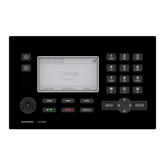
5 Installation and Mounting 5.1 LT-3110 Control Unit The LT-3110 Control Unit is the master unit in the system, supporting all external interfaces and the operational user interface. The LT-3110 Control Unit is designed for indoor mounting. Check the specifications in Appendix A: Specifications on page 45. Figure 2: LT-3110 Control Unit (front view) The LT-3110 Control Unit has the following interfaces: •... - Page 17 Figure 3: LT-3110 Control Unit (backside view) The LT-3110 Control Unit user interface, display and buttons, are described in User Interface (UI) on page 32. NOTE The LT-3110 Control Unit must be mounted as Console Mount or Bulkhead. Mounting and installation considerations: For optimum system performance, some guidelines on where to install or mount the LT-3110 Control Unit must be followed.
-
Page 18: 3120 Handset
5.2 LT-3120 Handset The LT-3120 Handset is the primary voice interface for the Alphatron LT-3100 Iridium. The LT-3120 Handset must be connected on the front of the LT-3110 Control Unit. The connector is illustrated in Figure 2 on page 16. -
Page 19: 3121 Cradle
5.3 LT-3121 Cradle The LT-3121 Cradle is used together with the LT-3120 Handset. The LT-3121 Cradle should be mounted next to the LT-3110 Control Unit, supporting the LT-3120 Handset. The LT-3121 Cradle specifications are available in Appendix A: Specifications on page 45. Figure 6: LT-3121 Cradle (front view) Figure 7: LT-3121 Cradle (backside view) The LT-3121 Cradle contains a magnet, to hold on to the LT-3120 Handset. -
Page 20: 3130 Antenna Unit
5.4 LT-3130 Antenna Unit The LT-3130 Antenna Unit is designed for outdoor mounting and connected to the LT-3110 Control Unit via a coaxial cable. The LT-3130 Antenna Unit specifications are available in Appendix A: Specifications on page 45. The LT-3130 Antenna Unit has an N connector (female) mounted, centred at the bottom of the antenna. - Page 21 LT-3130 Antenna Unit may be reduced, with no impact on the antenna performance. The performance of the LT-3130 Antenna Unit should be validated when the Alphatron LT-3100 Iridium is installed. The LT-3130 Antenna Unit shall me mounted minimum 1 m from MF-HF, VHF, and UHF antennas.
- Page 22 Figure 10: LT-3130 Antenna Unit – Separation to MF-HF, VHF, and UHF antennas The LT-3130 Antenna Unit must be installed with a 360° clear view of the sky. However, minor obstructions such as a mast will not degrade the antenna performance severely, if a separation distance larger than 15 times the diameter of the obstruction is kept.
-
Page 23: Bracket Mount, Antenna Unit
5.5 Bracket Mount, Antenna Unit The Bracket Mount (1.5" to 2.5" tube), Antenna Unit installation options are illustrated in Figure 12 and Figure 13. Figure 12: Bracket Mount (1.5" to 2.5" tube), Antenna Unit – vertical tube mount Figure 13: Bracket Mount (1.5" to 2.5" tube), Antenna Unit – horizontal tube mount 23 | Installation and Mounting... - Page 24 Bracket mount installation procedure: 1. Fasten the bracket mount to a tube (max. 2.5" tube) by using the two V-bolts and the M8 prevailing nuts, as illustrated in Figure 14 (max torque = 5.5 Nm) 2. Screw on the LT-3130 Antenna Unit and secure the antenna lock pinot (max torque = 1.2 Nm) 3.
-
Page 25: Pole Mount, Antenna Unit
Pole Mount, Antenna Unit The Pole Mount (1.5" tube), Antenna Unit is illustrated in Figure 15. Figure 15: Pole Mount (1.5" tube), Antenna Unit Pole mount installation procedure: 1. Feed the coaxial cable through the pole mount 2. Fasten the coaxial cable to the LT-3130 Antenna Unit (N connector) 3. - Page 26 Figure 16: Pole Mount (1.5" tube), Antenna Unit The Pole Mount (1.5" tube), Antenna Unit only support a 1.5" tube. The pinot NOTE screws (antenna and pole lock) torques are specified in Figure 16. The pole mount is made of milled aluminium (anodized). The pinot screws are made of A4 stainless steel.
-
Page 27: Interfaces
LT-3130 Antenna Unit. 6.1 DC input The Alphatron LT-3100 Iridium is designed to be used on 12 Vdc and 24 Vdc power buses (nominal). External DC power to the system is provided by connecting the 3 m power cable delivered by Alphatron Marine. - Page 28 The LT-3110 Control Unit must be powered off when inserting, changing, or NOTE removing the SIM card. The SIM card is hidden behind the rubber dust cover on the back side of the LT- 3110 Control Unit. Figure 17 shows an Iridium SIM card. The format is Mini-SIM (2FF) 25 x 15 mm. The SIM card must be removed from the full-sized card carrier by breaking the Mini-SIM out.
-
Page 29: Ethernet (Rj45)
6.4 Ethernet (RJ45) The LT-3110 Control Unit has an Ethernet LAN (RJ-45) interface, currently supporting service & maintenance. The Ethernet interface must be used to access the built-in web server, which is further described in section Web server on page 40. The LT-3110 Control Unit will automatically request and obtain an IP address when connected to a Local Area Network (LAN) with a DHCP server (e.g. - Page 30 where U is the control unit input voltage [V], P is the antenna unit power (10 W), and RCable is the total DC resistance [ꭥ/km] (sum of inner and outer conductor resistance). Figure 18: Coaxial Cable Total DC Resistance vs. Cable Length (12 Vdc and 24 Vdc) In Figure 18 two different input voltages (12 Vdc and 24 Vdc) illustrate the maximum length of the coaxial cable as a function of the DC cable resistance.
- Page 31 The cable lengths in Table 2 are calculated and corrected by reducing the input voltage by 10% (10.8 Vdc and 21.6 Vdc) to compensate for variation in the power source. The total DC resistance for the two cables shown in Table 3. Cable Type Inner Conductor DC Outer Conductor DC...
-
Page 32: User Interface (Ui)
7 User Interface (UI) The Alphatron LT-3100 Iridium is controlled from the LT-3110 Control Unit, which has the user interface for operating and configuring the system. The control unit has a 4.3" TFT-LCD display, supporting day and night modes. The layout of the display and buttons is illustrated in Figure 19. -
Page 33: Menu
• MENU button: The MENU button is used to open the main menu, as illustrated in Figure 20. The BACK, arrows, and ENTER buttons are used to navigate in the menu layout. Press the MENU button to exit the menu from anywhere in the menu tree (instead of multiple BACK button presses). -
Page 34: System Information
3100 Iridium will inform the user, if the system is not properly installed, or the system cannot register onto the Iridium® Network. Figure 21 is illustrating a Alphatron LT-3100 Iridium, which is registered on the Iridium® Network and ready to use. The Alphatron LT-3100 Iridium will provide user information in the status bar and status text (e.g. - Page 35 Table 6 is listing the system text and describing the status of the Alphatron LT-3100 Iridium. System Text Description System Status Initializing, please wait… The Alphatron LT-3100 Iridium is starting Not ready up. Please wait until the system text is updated. Searching for Iridium…...
- Page 36 Table 6: LT-3110 Control Unit – System Text The Alphatron LT-3100 Iridium can in addition to the system text also show an icon, which might be related to the status text, but not necessarily. The icon will be available in the icon line and might indicate a problem, but can also indicate a status of the system, or a service information to the user.
-
Page 37: Make A Voice Call
The Alphatron LT-3100 Iridium must be properly installed, connected, and configured before trying to establish a phone call. The Alphatron LT-3100 Iridium will inform the user about the status of the system, and whether the system is ready to initiate a call. -
Page 38: Off-Hook Mode
7.3.2 Off-hook mode In off-hook mode, the user starts to place the Alphatron LT-3100 Iridium into off-hook mode (ready tone available). The off-hook mode can be obtained in two ways: lifting the handset out of the cradle or pressing the green off-hook button, prior to typing any digits of the called number. In off-hook mode, the user will be met by a ready tone and the help text ‘Please enter number’... - Page 39 The voice call connection can be described with the following states: • State 1: Type in number • State 2: ‘Connecting…’ • State 3: ‘Duration: MM:SS’ – (if call is successfully connected) where MM are minutes and SS are seconds. The ‘Connecting…’...
-
Page 40: Web Server
8 Web server The LT-3110 Control Unit has a built-in webserver, which can be accessed from the Ethernet (RJ45) interface from the back side of the control unit. A PC must be connected to the control unit, either directly by connecting an Ethernet cable between a PC and the LT-3110 Control Unit, or by connecting the LT-3110 Control Unit to a Local Area Network (LAN), to where the PC is connected. -
Page 41: Dashboard
Navigate to the web server of the Alphatron LT-3100 Iridium, by following the instructions in section ‘Accessing the built-in web server’ on page 42. Select the ‘Software update’ webpage and click the ‘Browse…’... -
Page 42: Accessing The Built-In Web Server
Figure 27. Make sure, that you have typed in the correct IP address. 5. Press ‘Details’ and you will be presented for an extended page view (including a link), which will direct you to the Alphatron LT-3100 Iridium dashboard ‘Go on to the webpage (Not recommended)’. -
Page 43: Service & Repair
If the Alphatron LT-3100 Iridium for some reason does not work as described in this manual, contact the distributor or dealer, from where the product was originally bought. The distributor or dealer will have experience and know-how to assist with further technical support and troubleshooting. -
Page 44: Appendices
Appendices 44 | Appendices... -
Page 45: Appendix A: Specifications
Appendix A: Specifications Alphatron LT-3100 Iridium Certification & standards Maritime CE, RED, ISED, FCC, RCM, RoHS, Iridium® Vibration, operational IEC 60945 (sine) & proprietary Maritime Random profile Vibration, survival Proprietary Maritime Random profile Vibration, shock Proprietary Maritime profile (20 g, 11 ms) -
Page 46: Appendix B: Outline Drawing: Lt-3110 Control Unit
Appendix B: Outline Drawing: LT-3110 Control Unit 46 | Appendices... -
Page 47: Appendix C: Outline Drawing: Lt-3130 Antenna Unit
Appendix C: Outline Drawing: LT-3130 Antenna Unit 47 | Appendices... -
Page 48: Appendix D: Outline Drawing: Pole Mount, Antenna Unit
Appendix D: Outline Drawing: Pole Mount, Antenna Unit NOTE: The Pole Mount (1.5" tube), Antenna Unit interfaces to a tube of maximum 1.5" (38.1 mm), measured outer diameter. The total weight of the Pole Mount is 190 g (0.42 lbs). 48 | Appendices... -
Page 49: Appendix E: Outline Drawing: Bracket Mount, Antenna Unit
Appendix E: Outline Drawing: Bracket Mount, Antenna Unit NOTE: The Bracket Mount (1.5" to 2.5" tube), Antenna Unit interfaces to a tube of maximum 2.5" (63.5 mm), measured outer diameter. The total weight of the Bracket Mount is 714 g (1.57 lbs). 49 | Appendices... -
Page 50: Appendix F: Outline Drawing: Lt-3120 Handset
Appendix F: Outline Drawing: LT-3120 Handset 50 | Appendices... -
Page 51: Appendix G: Outline Drawing: Lt-3121 Cradle
Appendix G: Outline Drawing: LT-3121 Cradle 51 | Appendices... - Page 52 The Netherlands part of Alphatron Marine B.V. T +31 10 453 4000 F +31 10 453 4010 Document name : Alphatron LT-3100 Iridium service@jrc.com Document nr : 1027 www.jrc.am Version : V1.0...
Need help?
Do you have a question about the Alphatron LT-3100 Iridium and is the answer not in the manual?
Questions and answers