Table of Contents
Advertisement
Quick Links
Advertisement
Table of Contents

Related Manuals for Motic SWIFTLINE MAE-31R


Summary of Contents for Motic SWIFTLINE MAE-31R
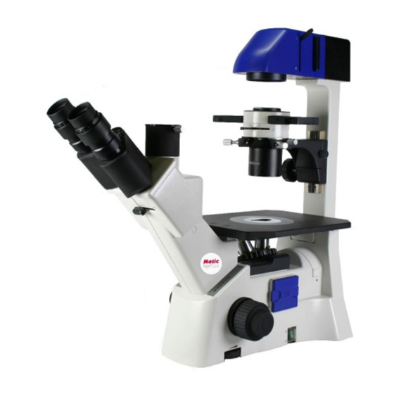
- Page 1 Inverted Microscope Instruction Manual Model MAE-31R...
-
Page 2: Table Of Contents
TABLE OF CONTENTS SECTION Specifications ........................ 4 III Setting-up the Instrument ....................5 IV Assembling the microscope Input voltage ..............6 Installing the lamp ........................6 Mounting the condenser ......................6 Installing Objectives ......................... 7 Mounting the eyepieces ......................7 Microscopic procedure Interpupillary distance adjustment .......... - Page 3 1. Lamp Socket Clamp Screw Knob 8. Objectives 2. Lamp House Cover Clamp Screw 9. Revolving Nosepiece 3. Annular Diaphragm 10. Coaxial Coarse/Fine Focus Knob 4. Condenser Diaphragm Lever 11. Torque Adjusting Ring 5. Condenser Focus Knob 12. Filter Retaining Ring 6.
-
Page 4: Specifications
1. Vertical Photo Port 2. Interpupillary Distance Scale 3. Diopter Adjustment Ring 4. Eyepiece 5. Optical Path Selector Lever 6. Filter Slider 7. Lamp House 8. Field Diaphragm Lever 9. Condenser Clamp Screw 10. Phase Slider 11. Condenser Clamp Holder Screw 12. -
Page 5: Setting-Up The Instrument
• Magnification Ratio: 40X – 400X • Eyepiece: N-WF 10X/22mm with diopter adjustment, +/- 5 diopter • Objectives: Infinity Corrected Magnification N.A. W.D. (mm) Plan Achromat 4X 0.10 23.5 Plan Achromat Phase 10X 0.25 Plan Achromat Phase LWD 20X 0.40 •... -
Page 6: Assembling The Microscope Input Voltage
• The location should be free from dust, moisture, chemical vapors and mechanical vibrations. • Do not situate the instrument in a warm and/or humid environment. • Locate the instrument where the operator’s line of vision is not directed towards a window, a lamp or a well-lit bright wall. -
Page 7: Installing Objectives
• Mount the condenser with the index marks and aperture diaphragm lever facing forward. Then secure it with the clamp screw. Condenser Phase Annular Diaphragm Slider Condenser Clamp Screw • Insert the phase annular diaphragm slider with centering hexagonal socket head screws facing the front. -
Page 8: Diopter Adjustment
• Adjust the interpupillary distance so that both the right and left field of view become one. • This adjustment will enable the user to observe the specimen with both eyes Diopter adjustment • Diopter adjustment compensates for differences in vision between the left and right eyes. In addition to making observation through both eyes easier, this adjustment also reduces the extent to which focusing is lost when the objective magnification is changed. -
Page 9: Centering The Lamp
• Turn the light intensity down and switch to the 10x objective. • Close the field of view diaphragm, 3/4 of the way. This lever is located on the lamp housing. This will close down the iris diaphragm in the lamp housing and become visible through the eyepiece field of view. - Page 10 • Close the condenser diagram down completely – moving lever to C. • Fully open the field of diaphragm and remove the diffuser filter slide. • Loosen, don’t remove the lamp socket clamp screw using the knob. This will allow the knob to move around with little resistance.
-
Page 11: Brightfield Microscopy
Brightfield microscopy • Set the Phase annular diaphragm slider in the centered open position. • Bring the specimen image into focus. • Adjust the opening of the field of view diaphragm, for normal observation the size of the diaphragm should be just outside the edge of the field of view. •... - Page 12 • Remove either eyepiece from the eyepiece tube and insert the phase centering telescope in its place. • Loosen the locking screw of the centering telescope eyepiece and slide out until both the phase plate image of the objective and the annular diaphragm image of the phase slider are in focus.
-
Page 13: Photo Procedure
• If the objective phase plate and the annular of the slider do not coincide, use the two hexagonal screwdrivers supplied with the microscope to bring the slider annular ring to the center of the phase plate, so that the image of the annular diaphragm is concentric with the phase plate image. •... - Page 14 • To attach the C0.5X adapter to your camera, simply screw onto your C-Mount camera. Remove the cap on the camera port of your microscope, by loosening the knurled screw. Then attach the C0.5X and lock into place with the knurled screw. •...
-
Page 15: Troubleshooting Table
VII Troubleshooting Table The troubleshooting table below contains the most frequently encountered problems and their possible causes. Optical and Operating Problems Problem Possible Cause Vignetting or uneven brightness Lamp not installed properly in the field of view or field of view Filter slider in intermediate position only partially visible Phase slider not in click-stop position... -
Page 16: Care And Maintenance
VIII Care and maintenance Lenses and filters • To clean lens surfaces or filters, first remove dust using compressed air. If dust still persists, use a soft/clean brush or gauze. • A soft gauze or lens tissue lightly moistened with pure alcohol should only be used to remove grease or fingerprints. -
Page 17: Warranty
IX Warrany Motic Swift Line Warranty The Motic Swift Line 5 Year Warranty assures that the microscope is guaranteed against defects in material and workmanship for 5 years from the purchase date of the product. Electrical components are covered for 1 year;...
Need help?
Do you have a question about the SWIFTLINE MAE-31R and is the answer not in the manual?
Questions and answers