Table of Contents
Advertisement
Available languages
Available languages
Quick Links
IT
IT
EN
EN
MANUALE D'ISTRUZIONE
MANUALE D'ISTRUZIONE
INSTRUCTION MANUAL
INSTRUCTION MANUAL
SALDATRICE MULTIFUNZIONE MIG-MAG/MMA/TIG
SALDATRICE MULTIFUNZIONE MIG-MAG/MMA/TIG
MIG-MAG/MMA/TIG MULTIFUNCTION WELDER
MIG-MAG/MMA/TIG MULTIFUNCTION WELDER
UNITECH 328
UNITECH 328
UNITECH 358C
UNITECH 358C
UNITECH 418 + X4
UNITECH 418 + X4
UNITECH 558 + X4
UNITECH 558 + X4
1
Advertisement
Table of Contents
Troubleshooting

Related Manuals for Helvi UNITECH 328


Summary of Contents for Helvi UNITECH 328
- Page 1 MANUALE D’ISTRUZIONE INSTRUCTION MANUAL INSTRUCTION MANUAL SALDATRICE MULTIFUNZIONE MIG-MAG/MMA/TIG SALDATRICE MULTIFUNZIONE MIG-MAG/MMA/TIG MIG-MAG/MMA/TIG MULTIFUNCTION WELDER MIG-MAG/MMA/TIG MULTIFUNCTION WELDER UNITECH 328 UNITECH 328 UNITECH 358C UNITECH 358C UNITECH 418 + X4 UNITECH 418 + X4 UNITECH 558 + X4 UNITECH 558 + X4...
-
Page 2: Table Of Contents
EN-7 MODALITA 2T/4T IT-14 UNIT CONTROLS EN-8 INDUTTANZA IT-14 FIGURA 6 - UNITECH 328: FRONT AND BACK VIEW OF VISUALIZZAZIONE PARAMETRI IT-14 THE COMPACT WELDING UNIT EN-8 SALDATURA MIG MANUALE (JOB LIST 10) IT-14 FIGURA 7 - UNITECH 358C: FRONT AND BACK VIEW OF... - Page 3 SYNERGIC MIG WELDING (JOB LIST 11-99) EN-14 RADID SETUP MENU - MIG EN-14 TABLE 2 EN-14 “CONSTANT VOLTAGE” FUNCTION EN-14 MMA WELDING EN-15 MMA MODE (UNITECH 328-358C - X4 WIRE FEEDER) EN-15 MMA MODE (UNITECH 418-558 GENERATORS) EN-15 TIG WELDING EN-15 TIG MODE (UNITECH 328-358C -...
-
Page 5: Norme Di Sicurezza
NORME DI SICUREZZA • L’area di saldatura deve essere fornita di INTRODUZIONE un’adeguata aspirazione locale che può de- rivare dall’uso di una cappa di aspirazione Assicuratevi che questo manuale venga letto o di un adeguato banco di lavoro predispo- e capito sia dall’operatore sia dal personale sto per l’aspirazione laterale, frontale e al di tecnico addetto alla manutenzione. -
Page 6: Shock Elettrico
combustibile (anche se svuotati) o in pressio- puter o altri sistemi di controllo; • Nell’area attorno alla macchina non devono • Alla fine della saldatura verificate che non essere presenti persone con stimolatori car- siano rimasti materiali incandescenti o fiam- diaci (peace-maker) o protesi per l’udito. -
Page 7: Introduzione
INTRODUZIONE Questo manuale è stato redatto per dare delle indicazioni sul funzionamento della saldatrice ed è stato pensato per offrire informazioni per un suo uso pratico e sicuro. Il suo scopo non è fornire istruzioni sulle tecniche di saldatura. Tutte i suggeri- menti dati sono indicativi e devo essere interpretati solo come linee guida. -
Page 8: Installazione
INSTALLAZIONE Note: COLLOCAZIONE • Il cavo di alimentazione deve essere control- lato periodicamente, per vedere se presenta Seguite le seguenti linee guida per la collo- segni di danneggiamento o di invecchiamen- cazione corretta della vostra saldatrice: to. Se non risultasse in buone condizioni non •... -
Page 9: Assemblaggio
– C – del generatore. le indicazioni in questo paragrafo. • Unitech 328: collegare il cavo di collega- • Controllare la tensione di linea e collegare la mento della torcia alla presa positiva sulla spina. -
Page 10: Caricamento Del Filo
• Allentare ed abbassare la manopola o le ma- CARICAMENTO DEL FILO nopole in plastica (A) e alzare le leve premifilo (B)(Fig.4). Estrarre eventuali residui di filo dalla guaina guidafilo. • Rilasciare il filo dalla bobina e tenetelo stretto con un paio di pinze in modo che non possa srotolarsi. -
Page 11: Collegamento Bombola Gas E Riduttore
Guaine in teflon/grafite. Sono particolarmen- COLLEGAMENTO BOMBOLA te indicate per la saldatura dell’alluminio, in GAS E RIDUTTORE quanto offrono la massima scorrevolezza all’avanzamento del filo. Assicuratevi che la macchina sia scolle- gata dalla presa. COLORE ROSSO GIALLO ATTENZIONE: Le bombole sono sotto DIAMETRO Ø... -
Page 12: Elementi Di Controllo E Allacciamento
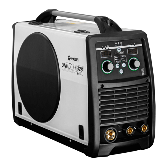
ELEMENTI DI CONTROLLO E ALLACCIAMENTO Figura 6 - Unitech 328: Generatore compatto portatile - vista frontale e posteriore Figura 7 - Unitech 358C: Generatore compatto carrellato - vista frontale e posteriore IT-8... -
Page 13: Figura 8 - Unitech 418-558: Generatore - Vista Frontale E Posteriore
Figura 8 - Unitech 418-558: Generatore - vista frontale e posteriore Figura 9 - Trainafilo esterno X4 - vista frontale e posteriore Figura 10 - Unità di raffreddamento ad acqua Smart XL - vista frontale e posteriore IT-9... -
Page 14: Interfaccia Di Controllo
L1 L2 L4 L5 L8 L9 L13-L14 Figura 11 - Unitech 328-358C-X4: Pannello di controllo del generatore compatto e del trainafilo separato Led Corrente [A] Led Spessore Se acceso indica che il display D1 sta visualizzando il Se acceso indica che il display D1 sta visualizzando valore di corrente espresso in Ampere. - Page 15 Led verde macchina alimentata Pulsante MODE Se acceso, la macchina è correttamente alimentata Selezione del processo di saldatura e pronta per l’uso, se lampeggiante indica che la Conferma variazione parametro macchina è temporaneamente non utilizzabile a causa di un allarme o di un cambio di processo di Pulsante SETUP saldatura.
-
Page 16: Figura 12 - Unitech 418-558: Pannello Di Controllo Del Generatore Con Trainafilo Separato
Figura 12 - Unitech 418-558: Pannello di controllo del generatore con trainafilo separato • Con traina filo esterno al generatore collega- to, i display D3 e D4 mostrano i parametri di saldatura durante l’utilizzo. Il pulsante T5 e la manopola E3 sono disabilitati, mentre i Led L17, L18, L19 sono attivi e replicano le funzioni dei Led L4, L5, L6. -
Page 17: Menu' Di Impostazione Iniziale (Basic Setup
Valore di • Premere il tasto T5 per 3s su Unitech 415- DEFAULT 558 e il tasto T2 su Unitech 328-358C e trai- Param_Reset nafilo X4 per confermare. Selezionabile solo da generatore con trainafilo H2o gestione dell’unità... -
Page 18: Saldatura A Filo
SALDATURA A FILO Collegare il cavo di massa alla presa negativa - - sul frontale della saldatrice e la pinza di massa al pezzo da saldare. Collegare la torcia MIG alla presa - - sul frontale della saldatrice facendo at- tenzione a non rovinare i contatti, quindi avvitate la ghiera di bloccaggio della torcia. -
Page 19: Soldadura Mma
(-) - MODALITA MMA (GENERATORI UNITECH il cavo di saldatura al positivo (+) - 418-558) MODALITA MMA (UNITECH 328-358C - Con il trainafilo scollegato dal generatore di TRAINAFILO X4) saldatura, abilitare la modalità MMA (Led L20) tenendo premuto il pulsante T5 per 3s.. -
Page 20: Salva E Richiama (Solo Mig
Richiamare premendo velocemente T4 SAVE finché appare la scritta SAV su D2. & RECALL finché appare la scritta REC su D2. RESET DI FABBRICA UNITECH 328-358C- TRAINAFILO X4 • Accendere il generatore tenendo premuto il pulsante T5 fino a quando sul display D3 sarà... -
Page 21: Suggerimenti Per La Saldatura E La Manutenzione
SUGGERIMENTI PER LA SALDATURA E LA MANUTENZIONE IMPORTANTE: assicuratevi che la macchina • Saldate sempre materiale pulito e asciutto. • Tenete la torcia a 45° rispetto al pezzo da sal- sia scollegata dalla presa di corrente prima dare con l’ugello a circa 6mm dalla superficie. di svolgere i seguenti interventi. -
Page 22: Lista Guasti Ed Inconvenienti Di Saldatura
Errore Causa / Soluzione “DAT”: nelle macchine con traino esterno indica a) verificare corretto fissaggio dei connettori del mancata comunicazione con la periferica esterna fascio cavi (Traina filo). b) controllare lo stato del fascio cavi c) spegnere e riaccendere il generatore. Se il problema persiste contattare assistenza “OUT”: all’accensione della macchina indica a) uscita in corto. - Page 23 Il filo si fonde incollandosi alla Punta ostruita. Cambiare la punta. punta guidafilo. Velocità di alimentazione del filo Aumentate la velocità di alimen- troppo bassa. tazione del filo. Punta di dimensioni sbagliate. Usate una punta di dimensioni corrette. La pinza e/o il cavo si surriscal- Cattiva connessione tra cavo e Stringere la connessione o sosti- dano.
- Page 24 IT-20...
-
Page 25: Safety Information
SAFETY INFORMATION INTRODUCTION • Be very carefull when welding any me- tals which may contain one or more of the follwing: Make sure this manual is carefully read and Antimony Beryllium Cobalt understood by the welder, and by the mainte- Manganese Selenium Arsenic... -
Page 26: Noise
• Wear dry gloves and clothing. Insulate • These welders use only inert or non-flammable yourself from the work piece or other parts of gases for welding arc protection. It is important the welding circuit. to choose the appropriate gas for the type of •... -
Page 27: Introduction
INTRODUCTION This manual was edited to give some indications on the operation of the welder and was thought to offer information for its practical and secure use. Its purpose is not teach welding techniques. All given suggestions are indicative and intended to be only guidelines. -
Page 28: Installation
INSTALLATION Notes: LOCATION • Periodically inspect supply cable for any cracks or exposed wires. If it is not in good Be sure to locate the welder according conditions, have it repaired by a Service Cen- to the following guidelines. tre. •... -
Page 29: Assembly
– C – of the power source. • Load the wire, connect the gas cylinder and • Unitech 328: connect the torch connection replace the wire liner if necessary, as descri- cable to the positive socket on the Voltage bed in this paragraph. -
Page 30: Wire Loading
pressure arms (B) of the feeder. (Extract the WIRE LOADING wire from the torch liner if some wire is left into the torch). • When the wire is disconnected, grasp it with pliers so that it cannot exit from the spool. If necessary, straighten it before inserting it in the wire input guide (C). -
Page 31: Gas Cylinder And Regulator Connection
wire liner, follow these instructions: GAS CYLINDER AND REGULATOR • Install the new liner and insert the wire liner CONNECTION collet (3) and the O ring (4). Ensure unit is powered off and unpluged • Mount the brass nut (1). •... - Page 32 UNIT CONTROLS Figure 6 - Unitech 328: Front and back view of the compact welding unit Figure 7 - Unitech 358C: Front and back view of the compact welding unit on wheels EN-8...
- Page 33 Figure 8 - Unitech 418-558: Front and back view of the power source Figure 9 - Front and back view of the X4 wire feeding unit Figure 10 - Front and Rear View of the Smart XL Water Cooler EN-9...
-
Page 34: Control Interface
L1 L2 L4 L5 L8 L9 L13-L14 Figure 11 - Unitech 328-358C and X4 wire feeder control panel Current LED [A] Thickness LED lights up when the current parameter is displayed on lights up when the parameter of the thickness of D1, this is expressed in Amps. - Page 35 Thermal alarm LED lights up if the generator overheats. Note: do not power off the generator and let it cool down. Inverter ON LED generator on welding Voltage LED [V] lights up when the parameter of the welding voltage is displayed on D2, this is expressed in [V]. Note: by welding, L7 is always ON and D2 displays the instantaneous arc voltage.
- Page 36 Figure 12 - Unitech 418-558 control panel • When the wire feeding unit is connected, the displays D3 and D4 show the welding para- meters during working. The T5 key and the E3 knob are disabled, L17, L18, L19 LEDs are active and replicate the functions of L4, L5, L6 LEDs.
-
Page 37: Initial Setup Menu
Selectable, only by the generator with separate wire • Hold the T5 key for 3s on Unitech 415-558 feeder not connected, in: and the T2 key on Unitech 328-358C and X4 wire feeder to confirm. • yes, to perform the factory reset, see section “Factory reset”... -
Page 38: Mig Wire Welding
MIG/MAG WELDING MIG WIRE WELDING Connect the earth cable to the Negative output terminal (Minus) - - on the front of the unit and the earth clamp to the workpiece. Plug the torch hose into the socket - - on the front of the welder having care to not damage the contacts and secure by hand screwing in the threaded con- nection. -
Page 39: Mma Welding
- and to setting is always possible only through E1 and E2 connect the electrode holder on the positive (plus) - on the wire feeder. MMA MODE (UNITECH 328-358C - X4 WIRE MMA MODE (UNITECH 418-558 GENERA- FEEDER) TORS) Enable the MMA mode (L11 LED) through the T2 key. -
Page 40: Save And Recall (Mig Only
Save by holding T4 until D2 displays the wor- • Recall by pressing T4 to read REC on D2. ding SAV. FACTORY RESET UNITECH 328-358C- X4 WIRE FEEDER ters (H2o, diGitAL_MEtEr, unit, StArt_ModE, droP _Cut, PLuS_ModE,VRD, Vcut e Param_ Reset) and select Param_Reset through T5. •... -
Page 41: Welding Hints And Maintenance
WELDING HINTS AND MAINTENANCE IMPORTANT: Disconnect from power • Always weld clean, dry and well prepared material. source when carrying out this operation. • Hold gun at a 45° angle to the workpiece with nozzle about 5 mm from the surface. •... -
Page 42: Troubleshooting
TROUBLESHOOTING This chart will assist you in resolving common problems you may encounter. These are not all the possible solutions. PROBLEM POSSIBLE CAUSE POSSIBLE SOLUTION No “life” from welder, display is Input cable or plug malfunction. Check for proper input cable connection Wrong size fuse. - Page 43 Wire pushes torch back from the Wire feed speed too fast Decrease wire feed speed workpiece Bad connection between earth Clean and deoxidate the contact clamp and workpiece. area of the earth clamp. The workpiece is excessively Brush carefully the point to be oxidized or painted.
- Page 44 EN-20...
- Page 46 SMALTIMENTO DI APPARECCHI DA ROTTAMARE DA PARTE DI PRIVATI NELL’UNIONE EUROPEA Questo simbolo che appare sul prodotto o sulla confezione indica che il prodotto non deve essere smaltito assieme agli altri rifiuti domesti- ci. Gli utenti devono provvedere allo smaltimento delle apparecchiature da rottamare portandole al luogo di raccolta indicato per il riciclag- gio delle apparecchiature elettriche ed elettroniche.
- Page 48 77613020...
Need help?
Do you have a question about the UNITECH 328 and is the answer not in the manual?
Questions and answers