
Related Manuals for Helvi GLOBUS 260HF


Summary of Contents for Helvi GLOBUS 260HF
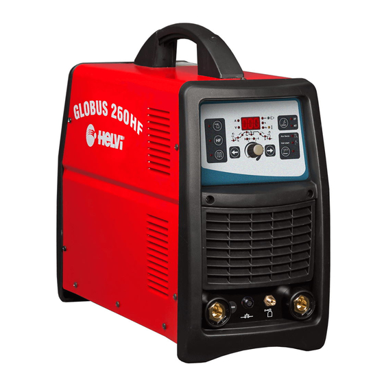
- Page 1 INSTRUCTION MANUAL MANUALE D’ISTRUZIONE WELDING INVERTER INVERTER DI SALDATURA GLOBUS 260HF 77611934...
-
Page 2: Table Of Contents
FOREWORD PREMESSA SAFETY SICUREZZA WARNINGS AVVERTENZE PERSONAL PROTECTION PROTEZIONE PERSONALE LIGHT RADIATIONS RADIAZIONI LUMINOSE WORKING AREA AREA OPERATIVA ELECTRIC SYSTEM IMPIANTO ELETTRICO FIRE PREVENTION PREVENZIONE D’ INCENDIO 21 PROTECTION GAS GAS DI PROTEZIONE NOISE RUMORE FIRST AID PRONTO SOCCORSO. INSTALLATION INSTALLAZIONE UNPACKING SBALLAGGIO... -
Page 4: Foreword
FOREWORD described in this manual is in accordance with RoHS EU Regulations 2002/95/CE of Thank you for purchasing our products. When 27 January 2003 regarding the restriction of assembled and used correctly, our welding the use of certain substances harmful for hu- generators are reliable and long-lasting and man health present in Electric and Electronic will help increase the productivity of your bu-... -
Page 5: Safety
SAFETY WARNINGS This manual contains instructions for the proper installation of the Electric Electronic Equipment (EEE) you have just purchased. The owner of an EEE must make sure that this document is read and understood by wel- ding technicians and their assistants and by maintenance technicians. -
Page 6: Light Radiations
PERSONAL PROTECTION the visible light and infrared and ultraviolet radiations). The helmet or the mask must be • Workers and their assistants must protect equipped with a protector whose degree of themselves by wearing closed, non-flamma- opacity will depend on the welding procedure ble protection coveralls, without pockets or and on the value of the electric arc current, rolled sleeves or legs. - Page 7 of the screen will depend on the welding pro- cess and on the value of the currents used), anti-UV goggles and, if necessary, masks with suitable protection filter (Fig. 4). Fig.4 Prior to any welding operation, clear the wor- king area from all chlorine solvents, which are normally used to clean or degrease the wor- king material.
-
Page 8: Electric System
Workers and their assistances must never Warning: Never touch the welding allow any parts of their bodies to come into cable or the electrode and the piece contact with metallic materials at high tempe- which is being welded at the same ratures or which are moving (Fig. -
Page 9: Protection Gas
Warning: Improper use of the gas, in particular in small spaces (cargo holds, tanks, reservoirs, silos etc), will expose the user to the following risks: 1 – Suffocation or intoxication with gas and gassy mixtures containing less than 20% of carbon dioxide (these gases replace oxygen in the air);... -
Page 10: Installation
INSTALLATION this document. The supply voltage of these generators is UNPACKING 400Vac +/-10% – 3Ph – 50/60Hz. If the po- wer grid corresponds to these values and is calibrated according to the maximum con- This electric appliance comes in a cardboard sumption of the generators (please see the box, complete with power cable (without a tables with technical information), simply con-... -
Page 11: Brief Introduction
BRIEF INTRODUCTION Your welding machine is an excellent DC pul- sed TIG arc welder which adopts the latest pulse width modulation (PWM) technology and insulated gate bipolar transistor (IGBT) inverter technology. It can realize TIG opera- tion and change work frequency to medium frequency so as to replace the traditional hulking work frequency transformer with the cabinet medium frequency transformer. - Page 12 11 ON/OFF Switch (back side) H TIG Welding Parameters 12 Remote control lead connector (back side) Pre Gas Time 13 Gas hose Connector (back side) Setting Range: 0.0 - 1.0 CONTROL PANEL Start Current (Is) Setting Range: 5 - 250 Amps Slope Up Time Setting Range: 0 - 10 sec.
-
Page 13: Stick Welding
STICK WELDING Avoid hammering the workpiece with the electrode since it may loose the coating and increase the arc striking difficulties. General information The electric arc may be described as a After striking the arc keep feeding the source of bright light and strong heat; electrode into the weld pool with an angle of in fact, the flow of electric current in the about 60°... -
Page 14: Tig Welding
TIG WELDING PULSED TIG The TIG process uses the electrical arc struck between the tungsten electrode of the torch and the work piece surface. In TIG welding the torch is always con- nected to the negative pole of the welder. 4-STROKE WELDING - DIAGRAM 1 Press and hold the gun switch, Elec- Welder preparation:... -
Page 15: Diagram 1
gun switch is pressed and held without relea- T3-T4 The output current slopes down to sing. minimum current (5A). Arc stops; adjustment Note: If the output pulse function is turned on, range of down slope time: 0~10S the output current is pulsed. T4-T5 Post flow time, adjustment range of Loosen the gun switch, the output cur- post flow time: 0-10.0S. -
Page 16: Ordinary Maintenance
FOOT PEDAL CONNECTION • Connect the foot pedal 14 pin plug to the rear panel of the machine into socket 12. • The foot pedal control is automatically acti- vated, the machine can work only in 2T mode. The arc striking is done pressing on the pedal. Current adjustment is done using the pedal, from its minimum value to Iw that was preset on the front panel before activating the remote... - Page 17 POSSIBLE WELDING DEFECTS DEFECT CAUSES SUGGESTIONS POROSITY Acid electrode on steel with high Use basic electrodes. sulphur content. Electrode oscillates too much. Move edges to be welded closer together. Workpieces are too far apart. Move slowly at the beginning. Workpiece being welded is cold. Lower welding current.
-
Page 18: Premessa
PREMESSA non possono tassativamente essere utilizzati per la ricarica delle batterie, lo scongelamento delle condotte d’ acqua, il riscaldamento di lo- Vi ringraziamo della fiducia accordataci con cali con l’aggiunta di resistenze, ecc…… l’acquisto di uno o più apparecchi riportati nel presente libretto. -
Page 19: Sicurezza
SICUREZZA AVVERTENZE Questo manuale contiene le istruzioni per una corretta installazione dell’ Apparecchia- tura Elettrica Elettronica (AEE) da Voi acqui- stata. Il proprietario di un prodotto AEE deve as- sicurarsi che il presente documento venga letto e capito dagli operatori in saldatura, dai loro assistenti e dal personale tecnico addet- to alla manutenzione. -
Page 20: Radiazioni Luminose
PROTEZIONE PERSONALE te) dalla luminosità dell’arco elettrico (abba- gliamento dell’arco da luce visibile e da ra- • Gli operatori e loro assistenti devono pro- diazioni infrarosse e ultraviolette). Il casco o teggere il proprio corpo indossando tute di la maschera devono essere dotati di un filtro protezione chiuse e non infiammabili, sen- protettore il cui grado di opacità... - Page 21 spondenti alla normativa EN 1598 (la scelta del colore di una tenda dipende dal processo di saldatura e dal valore delle correnti utiliz- zate) , di occhiali anti-UV e se necessario con una maschera dotata di filtro protettore adeguato (Fig. 4). Fig.4 Prima di saldare togliere dal luogo di lavoro tutti i solventi a base di cloro, normalmente...
-
Page 22: Impianto Elettrico
Il lavoratore ed i suoi assistenti non devono Attenzione: non toccare contempo- toccare con nessuna parte del corpo mate- raneamente il filo di saldatura o l’e- riali metallici ad elevata temperatura o in mo- lettrodo ed il pezzo da saldare. vimento (Fig. -
Page 23: Gas Di Protezione
Attenzione: le cattive condizioni di uti- lizzo dei gas in particolare in spazi ri- stretti (stive di navi, serbatoi, cisterne, silos, ecc.) espongono l’utilizzatore ai seguenti pericoli: 1_ di asfissia o di intossicazione con gas e miscele gassose contenenti meno del 20% di CO2, (questi gas sostituiscono l’ossigeno nell’aria), 2_ d’incendio e di esplosione con miscele gas-... -
Page 24: Sballaggio
INSTALLAZIONE se la rete corrisponde a questi valori ed è calibrata in funzione del consumo massimo dei generatori (ved. tab. dati tecnici) basta SBALLAGGIO collegare al cavo di alimentazione una spina L’apparecchiatura elettrica è fornita in scato- tripolare + terra di portata adeguata e inserir- la di cartone completa di cavo alimentazione la nella presa di distribuzione. -
Page 25: Caratteristiche Generali
CARATTERISTICHE GENERALI Il vostro generatore è un’eccellente salda- trice a TIG in corrente continua pulsata che adotta la tecnologia inverter a controllo PWM a media frequenza. E’ caratterizzato da alto rendimento e da dimensioni e peso ridotti tali da renderlo facilmente portabile. Le funzioni che lo rendono ottimo per ogni tipo di impiego sono: corrente di uscita constante, risposta rapida, innesco dell’arco con alta frequenza,... -
Page 26: Saldatura Ad Arco
6 Connettore Pulsante Torcia Una volta selezionato il parametro di salda- 7 Connettore tubo gas tura, il LED corrispondente all’unità di misu- 8 Presa dinse positiva ra (A, V, Tempo, Percentuale, Frequenza) si 9 Presa dinse negativa accende. 10 Cavo di alimentazione (retro) 11 Interruttore ON/OFF (retro) Nota: Per visualizzare la tensione premere il 12 Connettore comando a pedale (retro) -
Page 27: Qualita' Della Saldatura
rossa; i raggi ionizzati non vengono mai trodo nella stessa posizione con un angolo percepiti. Il calore prodotto dall’arco è uti- di circa 60° e muovendo da sinistra a destra lizzato nel processo di saldatura per fonde- potrete controllare visivamente la saldatura. re e unire assieme parti di metallo. -
Page 28: Saldatura A Tig
Velocità corretta di saldatura. 2T Lift - 2T HF La corretta velocità di saldatura consentirà di ottenere una saldatura dall’ ampiezza più adatta, senza onde o scanalature. SALDATURA A TIG Il processo a tig utilizza l’arco elettrico inne- TIG PULSATO scato tra l’elettrodo a tungsteno della torcia e la superficie del pezzo da saldare. -
Page 29: Schema 1
torcia. L’elettrovalvola si apre. Il gas di prote- Rilasciate il pulsante torcia, la corren- zione inizia ad uscire. te di uscita si abbassa. Se la funzione pulsato 0-T1 Tempo di pre Gas, da 0 a 1.0s. è attiva, la corrente della rampa di discesa T1-T2 Innesco dell’arco, la corrente di uscita sarà... -
Page 30: Collegamento Comando
NOTA: a) La lunghezza dell’arco varia generalmente da 3 a 6mm a seconda del tipo di giunto, tipo e spessore di materiale, ecc.. b) La torcia deve avanzare nella direzione della saldatura, senza movimenti laterali, mantenendo un angolo di 45° con il pezzo da saldare. -
Page 31: Possibili Inconvenienti
POSSIBILI DIFETTI DI SALDATURA DIFETTO CAUSE CONSIGLI POROSITA’ Elettrodo acido su acciao ad alto Usare elettrodo basico. tenore di zolfo. Oscillazioni eccessive dell’elet- Avvicinare i lembi da saldare. trodo. Distanza eccessiva tra i pezzi da Avanzare lentamente all’inizio. saldare. Pezzo in saldatura freddo. Diminuire la corrente di saldatura. - Page 32 SMALTIMENTO DI APPARECCHI DA ROTTAMARE DA PARTE DI PRIVATI NELL’UNIONE EUROPEA Questo simbolo che appare sul prodotto o sulla confezione indica che il prodotto non deve essere smaltito assieme agli altri rifiuti domesti- ci. Gli utenti devono provvedere allo smaltimento delle apparecchiature da rottamare portandole al luogo di raccolta indicato per il riciclag- gio delle apparecchiature elettriche ed elettroniche.
Need help?
Do you have a question about the GLOBUS 260HF and is the answer not in the manual?
Questions and answers