Table of Contents
Advertisement
Quick Links
Advertisement
Table of Contents

Subscribe to Our Youtube Channel
Related Manuals for Helvi TP 195


Summary of Contents for Helvi TP 195
- Page 1 OPERATING MANUAL TP 195...
-
Page 3: Safety Information
SAFETY INFORMATION 1.1 INTRODUCTION Make sure this manual is carefully read and understood by the welder, and by the maintenance and technical workers. 1.2 PERSONAL PROTECTION Welding processes of any kind can be dangerous not only to the operator but to any person situated near the equipment, if safety and operating rules are not strictly observed. -
Page 4: Electromagnetic Compatibility
dry wood or other insulating materials to move cables, if necessary away from the person. • Wear dry gloves and clothing. Insulate yourself from the work piece or other parts of the welding circuit. • Make sure the main line is properly grounded. •... -
Page 5: Installation
INSTALLATION 2.1 HANDLE AND WHEELS ASSEMBLY • Unpack the welder; • Screw the two casters (A) to the machine; • Insert the axle (B) through the holes at the rear of the welder and slide a wheel (C) on to each end followed by the retaining washers (D);... -
Page 6: Safety Instructions
2.6 SAFETY INSTRUCTIONS For your safety, before connecting the power source to the line, closely follow these instructions: • An adequate two-pole switch must be inserted before the main outlet; this switch must be equip- ped with time-delay fuses; • The connection with ground must be made with a two-pole plug compatible with the above men- tioned socket;... -
Page 7: Know Your Welder
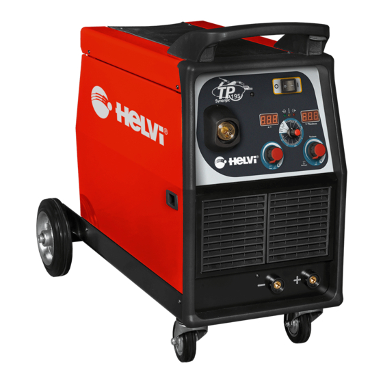
KNOW YOUR WELDER QUICK START Your new single phase inverter multi-function welder offers THREE WELDING FUNCTIONS in the same power source. These functions can be selected with knob (6) on the front panel of the unit: MIG (GMAW and FCAW) Welding with Gas and without Gas This welder offers the choice to weld in manual or synergic mode. - Page 8 Power switch indicator: This green LED lights when the welding machine is ON and is ready to work. In the event of an overvoltage supply the green LED blinks and the red LED (3) is ON. Thermal overload indicator: If the yellow LED is ON it indicates that the welder has overheated and the machine has automatically shut down.
-
Page 9: Torch Connection
STICK ELECTRODE WELDING (SMAW) 5.1 GETTING READY FOR STICK ELECTRODE WELDING (SMAW). • Select the Stick function (SMAW) with the Selector Switch (6) on the front panel. • Check the electrode packaging to determine the recommended polarity and connect the Electrode holder and ground clamp to the plus and minus Dinse sockets accordingly. -
Page 10: Replacing The Wire Liner
• When the wire is disconnected, grasp it with pliers so that it cannot exit from the spool. If necessary, straighten it before inserting it in the wire input gui- de (C). Insert the wire on the lower roll (D) and in the torch liner. -
Page 11: Gas Cylinder And Regulator Connection
7.1.5 GAS CYLINDER AND REGULATOR CONNECTION WARNING: Cylinders are highly pressurized. Handle with care. Serious accidents can result from improper handling or misuse of compressed gas cylinders. Do not drop the cylinder, knock it over, expose it to excessive heat, flames or sparks. Do not strike it against other cylinders. -
Page 12: Aluminum Welding
• Adjust the wire speed using the Left Knob (8) if necessary. Possible variation is +/-40% on the base value adjusted by default ( “0” on the display). • Bring the torch close to the work piece and press the trigger. Wire feeder Slope-Up Time (Min. -
Page 13: Troubleshooting
10.0 TROUBLESHOOTING This chart will assist you in resolving common problems you may encounter. These are not all the possible solutions. POSSIBLE CAUSE PROBLEM POSSIBLE SOLUTION No “life” from welder Input cable, plug or main switch Check for proper input cable connection malfunction. - Page 14 Use correct size contact tip. Wrong size contact tip. BBT time is too long. Adjust BBT time with the potentiometer located on the spool compartment (18). Workpiece clamp and/or Tighten connection or replace cable. Bad connection from cable to cable gets hot. clamp.
- Page 15 Figure 9...
-
Page 16: Wiring Diagram
13.0 WIRING DIAGRAM... - Page 20 77611864...
Need help?
Do you have a question about the TP 195 and is the answer not in the manual?
Questions and answers