
Related Manuals for SeaLevel ULTRA 530.PCI


Summary of Contents for SeaLevel ULTRA 530.PCI
- Page 1 ULTRA 530.PCI User Manual | 7101 © Sealevel Systems, Inc. 7101 Manual | SL9160 9/2021...
-
Page 2: Table Of Contents
APPENDIX B – HOW TO GET ASSISTANCE.................................. 21 APPENDIX C – ELECTRICAL INTERFACE ..................................22 APPENDIX D – ASYNCHRONOUS COMMUNICATIONS ............................. 24 APPENDIX E – SILK-SCREEN ......................................25 APPENDIX F – COMPLIANCE NOTICES..................................26 WARRANTY ............................................27 © Sealevel Systems, Inc. 7101 Manual | SL9160 9/2021... -
Page 3: Introduction
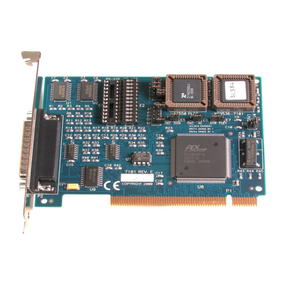
Introduction Overview The Sealevel Systems ULTRA 530.PCI is a one channel PCI Bus serial I/O adapter for the PC and compatibles. It provides one field selectable RS-232/422/485/530 serial port supporting asynchronous data rates up to 460.8K bps as well as isochronous data rates up to the speed of the supplied clock. Now, with this card, you can use your standard communications software and connect over a clocked digital communications line. -
Page 4: Before You Get Started
Before You Get Started What’s Included The ULTRA 530.PCI is shipped with the following items. If any of these items are missing or damaged, contact the supplier. • ULTRA 530.PCI Serial I/O Adapter Advisory Conventions Warning The highest level of importance used to stress a condition where damage could result to the product, or the user could suffer serious injury. -
Page 5: Card Setup
Some communication software packages refer to RS-485 as RTS enable or RTS block mode transfer. One of the unique features of the ULTRA 530.PCI is the ability to be RS-485 compatible without the need for special software or drivers. This ability is especially useful in Windows, Windows NT, and OS/2 environments where the lower level I/O control is abstracted from the application program. - Page 6 RS-485 Mode Examples (Header E4) Figure 1- Header E4, RS-422 Figure 2 – Header E4, RS-485 ‘Auto’ Enabled, with ‘No Echo’ Figure 3 - Header E4, RS-485 ‘Auto’ Enabled, with ‘Echo’ © Sealevel Systems, Inc. 7101 Manual | SL9160 9/2021...
- Page 7 Figure 6 – Header E4, RS-485 ‘DTR’ Enabled, with No Echo Address and IRQ selection The ULTRA 530.PCI is automatically assigned I/O addresses and IRQs by your motherboard BIOS. Only the I/O address may be modified by the user. Adding or removing other hardware may change the assignment of I/O addresses and IRQs.
- Page 8 Adds or removes the 120-ohm termination. Connects the TX+ to RX+ for RS-485 two wire operation. Connects the TX- to RX- for RS-485 two wire operation. Figure 7 - Headers E3, Line Termination © Sealevel Systems, Inc. 7101 Manual | SL9160 9/2021...
- Page 9 Electrical Interface Selection Each port on the ULTRA 530.PCI has the ability to be used in either RS-232 or RS-422/485. This is selectable via four 24 pin DIP-shunts at E1-E4. Please use the following illustration to aid in the configuration of your electrical interface.
- Page 10 CARD SETUP, CONTINUED Clock Modes The ULTRA 530.PCI employs a unique clocking option that allows the end user to select from divide by 4 and divide by 1 clocking modes. These modes are selected at Header E8. To select the Baud rates commonly associated with COM: ports (i.e., 2400, 4800, 9600, 19.2, … 115.2K Bps) place the jumper in the divide by 4 mode (silk-screen DIV4).
- Page 11 If your communications package allows the use of Baud rate divisors, choose the appropriate divisor from the following table: For this Data Rate Choose this Divisor 1200 bps 2400 bps 4800 bps 9600 bps 19.2K bps 38.4K bps 57.6K bps 115.2K bps 230.4K bps 460.8K bps © Sealevel Systems, Inc. 7101 Manual | SL9160 9/2021...
- Page 12 Figure 12 – Header E5, Modem Control Signal DSR selected as input Figure 13 - Header E5, Clock Signal RXC selected as input Figure 14 - Header E6, Modem Control Signal RI selected as input © Sealevel Systems, Inc. 7101 Manual | SL9160 9/2021...
- Page 13 Figure 15 - Header E6, Clock Signal TXC selected as input TSET Figure 16 - Header E7, Modem Control Signal DTR selected as output TSET Figure 17 - Header E7, Clock Signal TSET selected as output © Sealevel Systems, Inc. 7101 Manual | SL9160 9/2021...
-
Page 14: Installation
Linux releases. Also included is a series of files explaining proper Linux syntax and typical Linux serial implementations. For the most up to date information on the QNX4 software support, please call Sealevel Systems’ Technical Support, (864) 843-4343. Our technical support is free and available from 8:00AM-5PM Eastern Time, Monday through Friday. - Page 15 4. Gently insert the PCI adapter into the slot. Make sure that the adapter is seated properly. 5. Replace the screw. (This is required to ensure FCC Part 15 compliance.) 6. Replace the cover. 7. Connect the power cord Installation is finished. © Sealevel Systems, Inc. 7101 Manual | SL9160 9/2021...
-
Page 16: Technical Description
16C850 UART’s that provide deeper FIFO’s (32-, 64-, 128-bytes respectively). One other unique feature of the ULTRA 530.PCI is the support for the Oxford Semiconductor 16C950. This chip features a deep FIFO (128-bytes transmit and receive), automatic RS-485 driver enables, and the ability to receive a clock for isochronous communications. - Page 17 Input Transmit Clock Input Receive Clock Input Data Carrier Detect Input Ring Indicator Input Transmit Data Output Request To Send Output TSET Transmit Signal Element Timing Output Data Terminal Ready Output © Sealevel Systems, Inc. 7101 Manual | SL9160 9/2021...
- Page 18 These assignments meet the EIA/TIA/ANSI-530 DTE specification with the exception of Ring Indicator which is not specified. It has been included here for compatibility with systems requiring Ring Indicator. Always terminate any unused signals. This allows for maximum data thru-put. © Sealevel Systems, Inc. 7101 Manual | SL9160 9/2021...
-
Page 19: Specifications
10 to 90% R.H. Non-Condensing Manufacturing All Sealevel Systems Printed Circuit boards are built to UL 94V0 rating and are 100% electrically tested. These printed circuit boards are solder mask over bare copper or solder mask over tin nickel. Power Consumption... -
Page 20: Appendix A - Troubleshooting
Technical Support. Ensure that the Sealevel Systems SeaCOM software has been installed on the machine, so that the necessary files are in place to complete the installation. To confirm installation, click on the Windows ‘Start’... -
Page 21: Appendix B - How To Get Assistance
If possible, please have the adapter installed in a computer ready to run diagnostics. Sealevel Systems provides an FAQ section on its web site. Please refer to this to answer many common questions. This section can be found at http://www.sealevel.com/faq.asp. -
Page 22: Appendix C - Electrical Interface
1 driver and up to 32 receivers on the line at once. RS-422 signal levels range from 0 to +5 volts. RS-422 does not define a physical connector. © Sealevel Systems, Inc. 7101 Manual | SL9160 9/2021... - Page 23 The RS-530 specification defines two types of interface circuits, Data Terminal Equipment (DTE) and Data Circuit-Terminating Equipment (DCE). The Sealevel Systems adapter is a DTE interface. © Sealevel Systems, Inc.
-
Page 24: Appendix D - Asynchronous Communications
The communication parameters are baud rate, parity, number of data bits per character, and stop bits (i.e., 9600, N, 8, 1). © Sealevel Systems, Inc. 7101 Manual | SL9160 9/2021... -
Page 25: Appendix E - Silk-Screen
Appendix E – Silk-Screen 3.5" 3.5" 4.9" 3.175" 3.175" © Sealevel Systems, Inc. 7101 Manual | SL9160 9/2021... -
Page 26: Appendix F - Compliance Notices
Always use cabling provided with this product if possible. If no cable is provided or if an alternate cable is required, use high quality shielded cabling to maintain compliance with FCC/EMC directives. © Sealevel Systems, Inc. 7101 Manual | SL9160 9/2021... -
Page 27: Warranty
Sealevel's commitment to providing the best I/O solutions is reflected in the Lifetime Warranty that is standard on all Sealevel manufactured I/O products. We are able to offer this warranty due to our control of manufacturing quality and the historically high reliability of our products in the field. Sealevel products are designed and manufactured at its Liberty, South Carolina facility, allowing direct control over product development, production, burn-in and testing.
Need help?
Do you have a question about the ULTRA 530.PCI and is the answer not in the manual?
Questions and answers