Advertisement
Quick Links
Advertisement

Subscribe to Our Youtube Channel
Related Manuals for icetro IM-770-AN


Summary of Contents for icetro IM-770-AN
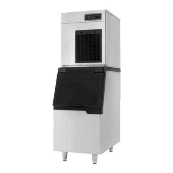
- Page 1 IM-770-AN/F INSTALL & SERVICE MANUAL...
- Page 2 Ice Machine Specs...
- Page 3 Ice Machine Specs...
- Page 4 All equipment leaves our distribution points in new condition. When receiving new equipment, please pay close attention to the packaging for any damage to the crating. If there appears to be any exterior damage, please either note the damaged on the delivery bill of lading OR refuse it. Failure to note damage on BOL or refuse damaged equipment means that the receiver accepts all liability for damaged equipment.
-
Page 5: Proper Installation
12. If you are installing the ice maker on top of a dispenser, the dispenser manufacturer must provide the top kit to prevent leaks and bin problems. Additionally, an Icetro thermostat kit is required (ITS-150-KIT). Proper Installation... - Page 6 Ensure the ICE-OFF-WASH switch is set to ‘ICE’. Ice will begin to enter the ice storage bin after 3 minutes of the compressor & condenser fan being energized. The size of your ice storage bin, plus the ambient & water temps will Determine how long it will Proper Installation take to fill the bin.
- Page 7 Seismic Bracket Air Deflector Install machine on an ice storage bin and ensure both are level to eliminate improper operation. Additionally, it is recommended to use the supplied seismic brackets to secure the ice machine and bin together. Proper Installation An air deflector is included with self-contained, air-cooled models IM-0770 to prevent exhausted air from returning back to the condenser.
-
Page 8: Sequence Of Operation
IM-0770-AN/AF Sequence of Operation Start-Up Sequence Power switch set to the “ICE” position: • Gear motor, inlet water valve, and bypass valve is energized simultaneously. • Bypass valve stays energized for 50 seconds. • Bypass valve is de-energizes for 10 seconds. •... -
Page 9: Led Functions
IM-0770 LED Functions... - Page 10 Set the power switch on the front of the ice machine to the “OFF” position. • While ice machine is underway, all refrigeration stops, but the motor continues to run for an additional 60 seconds to protect the motor from any remaining water or ice that may be in the cylinder. •...
- Page 11 IM-0770-AN/AF Drop Zone Chart. (A)11.3” (B)11.4” (C)22” (D)25.4” Ice Outlet is 5.4” ID IM-0770 Drop Zone...
-
Page 12: Wiring Diagram
IM-0770 Wiring Diagram... - Page 13 Dump Water Gear Valve Valve Motor Heater Bypass Cond. Main Valve Comp Power Switch Float Switch Mode Switch Motor Tachometer Thermistor Display IM-0770 Thermistor...
-
Page 14: Key Features
Urethane insulated & sealed to prevent moisture penetration, which can rupture the refrigeration serpentine. Non-vented gear box to prevent lubrication breakdown. IM-0770 Key Features... - Page 15 Flake & Nugget Extruder Heads are Interchangeable • Carbon bearing is pressed inside of extruder head. • No grease or maintenance to prevent major Flaker Extruder mechanical breakdowns. & Breaker • Simply check extruder/bearing & replace if required. Extruder with Carbon Bearing Pressed Into Place IM-0770 Nugget Extruder...
- Page 16 Spiral circular cutting blade designed to reduce gearbox torque and provide greater durability. User manual state that 17” of clearance is required to service and remove auger on the IM-0770! Tapered flight reduces torque. Spring loaded carbon/ceramic mechanical seal. Pin cut spring insertion in bottom of flight.
- Page 17 Water Level Float Switch Water tank The water Water tank Empty only fills to Full the lower part. Float Sensor Water valve Physical state High water level Low water level operation sensor sensor 0(Close) 0(Close) Water tank Empty The current The water only fills to the lower 0(Close) 1(Open)
- Page 18 Poor maintenance, leaking gaskets/bolts, or a plugged drain can destroy a machine: If bolts at the top extruder or lower housing assembly leak, scale can build up on the urethane insulation, the lower housing assembly, and/or the gear box and destroy those parts. Should the drain pan’s drain line become plugged, it will overflow and cause scale to greatly damage unit.
- Page 19 Visually inspect all hex head bolts holding lower housing assembly to evaporator barrel for leaks. Use caution during reassembly to ensure all new bolts are cross tightened evenly. Drains have been enlarged to prevent overflow & scale buildup on critical parts. IM-0770 Service Tips Note: Evaporator barrel bolts are reverse thread to remove...
- Page 20 Type Cause Indicator Action to Take Bin Full Storage bin is full of ice. ‘Full’ indicator light is on. None – Enjoy your ice! Check water supply. Check water reservoir is full. Water Supply Water is not being supplied on time. ‘No Water’...
- Page 21 IM-0770 P/T Chart & Cycle Times...
- Page 22 IM-0770 Parts Breakout...
- Page 23 IM-0770 Parts Breakout...
- Page 24 IM-0770 Parts Breakout...
- Page 25 IM-0770 Parts Breakout...
- Page 26 IM-0770 Parts Breakout...
- Page 27 IM-0770 Parts Breakout...
- Page 28 IM-0770 Parts Breakout...
- Page 29 IM-0770 Parts Breakout...
-
Page 30: Suggested Maintenance Schedule
Suggested Maintenance Schedule Maintenance intervals will vary with ambient & water conditions. These are only suggestions. WEEKLY YEARLY Clean These Items Weekly Inspect These Parts Yearly ● Water Dump Solenoid ● Air filters are located on the front ● Water Inlet Solenoid and left-side panels. - Page 31 Suggested Maintenance Schedule Maintenance intervals will vary with ambient & water conditions. These are only suggestions. EVERY 3 Preventative Maintenance - Technicians Only YEARS ● Inspect the inside of the evaporator cylinder for wear, cracks, etc. ● Inspect the auger for wear, cracks, etc. & replace if necessary. ●...
-
Page 32: Cleaning Solution
Suggested Cleaning Procedure Cleaning Solution Use a nickel-safe ice machine cleaning solution and mix 16oz of cleaner for ever 6 liters of water. Cleaning Procedure 1. Close the water supply valve. 2. Set the power switch to the ‘DRAIN’ position. 3. - Page 33 Suggested Cleaning Procedure Cleaning Procedure Continued a) Remove the float switch from the cover of the reservoir. b) Clean the float switch with cleaning solution. c) Completely rinse the float switch with clean water. d) Reassemble the float switch back in place. 11.Turn on the circuit breaker and set the power switch to the ‘ICE’...
- Page 34 Reliable Operations & Longevity • Ice is digested and sanitation and bacteria control must be checked to ensure the machine is safe by keeping it clean. • 80-85% of machine failures are due to poor install, lack of cleaning, inadequate water treatment, or airborne slime (Bacteria).
- Page 35 HOW DOES CITRYNE FILTRATION WORK The ideal pH level of drinking water is between 6 and 8.5. The pH value of water is used to determine whether water is hard or soft. Pure water has a pH of 7, and water lower than 7 pH is considered acidic.
- Page 36 THANK YOU 1/15/2022...
Need help?
Do you have a question about the IM-770-AN and is the answer not in the manual?
Questions and answers
How to reset machine when all lights are blinking
To reset the Icetro IM-770-AN machine when all lights are blinking, follow these steps:
1. Unplug the machine from the power source.
2. Wait for at least 1 hour.
3. Plug the machine back in.
4. Check for any error indicators and inspect components such as the fan motor, thermistors, and refrigerant charge if necessary.
If the issue persists, further troubleshooting may be needed.
This answer is automatically generated