
Subscribe to Our Youtube Channel
Related Manuals for SANUS VuePoint FLF118


Summary of Contents for SANUS VuePoint FLF118
- Page 1 FLF 118 INSTRUCTION MANUAL We’ll Make It Stress-Free If you have any questions along the way, just give us a call. 1-888-333-9952. We’re ready to help! Scan for easy install video san.us/54...
- Page 2 IMPORTANT SAFETY INSTRUCTIONS – SAVE THESE INSTRUCTIONS – PLEASE READ ENTIRE MANUAL PRIOR TO USE Before getting started, let’s make sure this mount is perfect for you! Para Español ver página 26 Does your TV weigh more than 100 lbs. (45.3 kg) including accessories? No —...
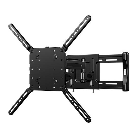
- Page 3 Dimensions TV INTERFACE [mm] 200mm 7.87in 400mm 15.75in 680.9mm 26.81in 100mm 3.94in 600mm 23.62in WALL PLATE TOP VIEW - SWIVEL SIDE VIEW - EXTENDED / TILT 120.5mm 4.74in 12deg 5deg 8.4mm 406.4mm .33in 16.00in 31deg 31deg 155.5mm 6.12in 80mm 3.15in 571.2mm 463.8mm 22.49in...
-
Page 4: Supplied Parts And Hardware
Supplied Parts and Hardware WARNING: This product contains small items that could be a choking hazard if swallowed. Before starting assembly, verify all parts are included and undamaged. If any parts are missing or damaged, do not return the damaged item to your dealer;... - Page 5 STEP 1 Attach TV Bracket to TV 1.1 Measure Your TV Hole Pattern Measure the width and height of your TV hole pattern in cm. Record your measurements: Width ________cm X Height ________cm 75 mm = 7.5 cm ≈ 3 in. 100 mm = 10 cm ≈...
- Page 6 1.2 Assemble Your TV Bracket 15.75 [cm] Based on your TV hole pattern measurements, determine which [40.0] TV hole pattern TV bracket configuration to use, A, B, C, or D. measurement (cm) 11.81 30.0 x 30.0 [30.0] 40.0 x 40.0 [cm] 15.75 TV hole pattern...
- Page 7 [cm] [cm] 15.75 TV hole pattern TV hole pattern measurement (cm) measurement (cm) [40.0] 60.0 x 40.0 40.0 x 20.0 23.62 [60.0] 7.87 [20.0] 15.75 [40.0] 20.0 x 40.0 7.87 7.87 [20.0] [20.0] 15.75 15.75 [40.0] [40.0] Assemble TV bracket extenders onto TV bracket as illustrated.
- Page 8 1.3 Select TV Screw Diameter 1.4 Select TV Screw Length Standard configurations are shown. For special If your TV has a flat back AND you want your TV closer to the applications, or if you Hand thread screws into the threaded inserts wall, use the shorter screws.
- Page 9 1.5 Attach TV Bracket Position your TV bracket configuration (A, B, C, or D) over your TV hole pattern - making sure the bracket is centered over the TV hole pattern and level. Secure bracket using your screw/washer (Flat Back) or spacer/screw/washer (Round Back / Extra Space) selection. IMPORTANT: Ensure TV bracket is securely fastened before moving on to the next step.
-
Page 10: Step 2 Parts And Hardware
Contact Customer Service at 1-888-333-9952 hazard if swallowed. to have the kit shipped directly to you. Wall Plate Template Lag Bolts WELCOME AND THANKS FOR CHOOSING SANUS VUEPOINT THIS WAY UP GET STARTED THIS IS YOUR DRILLING VIEWING HEIGHT YOU’RE REALLY GOING... - Page 11 STEP 2.1 Assemble Your Wall Plate 8 mm wrench...
- Page 12 STEP 2.2 Attach Wall Plate to Wall Wood Stud Option CAUTION: Avoid potential personal injuries and property damage! ● Drywall covering the wall must not exceed 5/8 in. (16 mm) ● Minimum wood stud size: common 2 x 4 in. (51 x 102 mm) nominal 1½ x 3½ in. (38 x 89 mm) ●...
- Page 13 Drill pilot holes using a 7/32 in. (5.5 mm) diameter drill bit. Remove wall plate template IMPORTANT: Be sure to drill into the center of the stud. IMPORTANT: Pilot holes must be drilled to a depth of 3½ in. (89 mm). Install wall plate assembly using four lag bolts .
- Page 14 STEP 2.2 Attach Wall Plate to Wall Solid Concrete or Concrete Block Option CAUTION: Avoid potential personal injuries and property damage! Concrete Installation Kit CMK1 is NOT INCLUDED ● Mount the wall plate assembly directly onto the concrete surface Contact Customer Service at 1-888-333-9952 ●...
- Page 15 and insert four anchors C3 (Fischer UX 10 x 60R - included in the Concrete Installation Kit CMK1*). Remove the wall plate template CAUTION: Be sure the anchors C3 are seated flush with the concrete surface. Install wall plate assembly using four lag bolts C1 and four washers C2 (use ONLY the lag bolts and washers from the Concrete Installation Kit CMK1*).
- Page 16 STEP 3 Attach Arm to Wall Plate Before starting assembly, verify all parts are included and undamaged. If any parts are missing or damaged, do not return the damaged item to HEAVY! You may need assistance with this step. your dealer; contact Customer Service. Never use damaged parts! STEP 3 Parts and Hardware WARNING: This product...
- Page 17 CAUTION: Avoid potential personal injury or property damage! Tighten M5 wall plate screws using the 4 mm hex key For concrete installations, the base of the arm must remain centered in the wall plate assembly. secure arm to wall plate assembly. CAUTION: Avoid potential injury or property damage! M5 wall plate screws must be installed to secure the arm...
- Page 18 STEP 4 Hang TV onto Arm Before starting assembly, verify all parts are included and undamaged. If any parts are missing or damaged, do not return the damaged item to HEAVY! You may need assistance with this step. your dealer; contact Customer Service. Never use damaged parts! Hang the TV bracket onto the arm by first hooking the top...
-
Page 19: Manage Cables
Manage Cables Cables can be routed through the cable channels on the top and Using the 4mm hex key , secure the TV bracket to the arm bottom of the arm with screw and washer CAUTION! Avoid potential injury or property damage! This screw must be installed to secure the TV onto the arm TOP VIEW... -
Page 20: Cable Management
Manage Cables - Cable Tunnel WARNING: This product contains small items that could be a choking hazard if swallowed. Before starting assembly, verify all parts are included and undamaged. If any parts are missing or damaged, do not return the damaged item to your dealer;...
Need help?
Do you have a question about the FLF118 and is the answer not in the manual?
Questions and answers