Table of Contents
Advertisement
Available languages
Available languages
Quick Links
Advertisement
Chapters
Table of Contents

Related Manuals for Hinkley DRAFTSMAN 60


Summary of Contents for Hinkley DRAFTSMAN 60
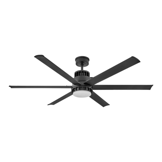
- Page 1 60” DRAFTSMAN INDOOR / OUTDOOR LED FAN CONTROL DC MOTOR WIFI CEILING FAN INSTRUCTION MANUAL PAIR WITH HINKLEY APP DOWNLOAD ON APP STORE or GOOGLE PLAY hinkley.com HINKLEY CUL Model No. 60-DRAT...
- Page 2 SO WE’RE HERE IF YOU HAVE A QUESTION, NEED SOME HELP OR WANT TO CHAT ABOUT OUR PRODUCTS, SEND SUGGESTIONS OUR WAY TOO - WE’RE ALWAYS LOOKING TO MAKE YOUR EXPERIENCE WITH HINKLEY A POSITIVE ONE. > SERVICE@HINKLEY.COM > 800.HINKLEY >...
-
Page 3: Table Of Contents
INSTALLING THE HANGING BRACKET TROUBLESHOOTING HANGING THE FAN ENERGY GUIDE ELECTRICAL CONNECTIONS SPECIFICATIONS FINISHING THE INSTALLATION HINKLEY APP / WIFI INSTALLING THE BLADES WARNING: Read and follow these instructions carefully and be mindful of all warnings shown throughout. ©2022 Hinkley Lighting, Inc. hinkley.com... - Page 4 If you think batteries might have been swallowed or placed inside any part of the body, seek immediate medical attention. WARNING: To reduce the risk of fire or electric shock, this fan should only be used with fan speed control part no. JY1126T manufactured by Satellite Electronic (Zhongshan) Ltd. Note: Suitable for use in wet locations. hinkley.com...
-
Page 5: Important Safety Precautions
These factors must be supplied by the person(s) installing, caring for and operating the unit. TOOLS & MATERIALS REQUIRED • PHILLIPS SCREWDRIVER • FLAT SCREWDRIVER • WRENCH OR PLIERS • WIRE CUTTERS • STEP LADDER • WIRING SUPPLIES AS REQUIRED BY ELECTRICAL CODE ©2022 Hinkley Lighting, Inc. hinkley.com... -
Page 6: Unpacking Your Fan
Screws, Cradle B (for flat wall use only) Hardware Bag Hanging bracket hardware, Safety cable hardware, Blade screws, MH905360 Spacers, Blade bracket screws, Blade balancing kit NOTE: Design of parts shown above may look slightly different for your specific model of fan xx=FAN FINISH hinkley.com... -
Page 7: Preparation
This will enable you to remove the mounting Hanger bracket. Bracket Attach hanging bracket to outlet box using screws provided with the outlet box. Flat Washer Spring Washer Outlet Box Screw Figure 2 ©2022 Hinkley Lighting, Inc. hinkley.com... -
Page 8: Hanging The Fan
Securely tighten set screw against downrod using a large flat-head screwdriver to ensure a tight fit against downrod. Tighten nuts against mounting collar. Figure 1 Hook-up (5) Wires Downrod Security Screws Mounting Collar Downrod pin Cotter pin Top of Fan Body Figure 2 hinkley.com... - Page 9 Feed the end of the cable into the clamp and pull as much cable through as possible. Safety Cable Loop Firmly tighten screw in the clamp. Cut off excess cable. Wood Screw And Washer Safety Cable Figure 5 ©2022 Hinkley Lighting, Inc. hinkley.com...
-
Page 10: Electrical Connections
Connect the BLACK building supply wire to the BLACK receiver wire. ORANGE GRAY BROWN Connect the WHITE receiver neutral wire to the WHITE building WHITE neutral wire. BLUE Connect the COPPER building ground wire to the 4 YELLOW/ Figure 3 GREEN ground wires from the fan and receiver. hinkley.com... -
Page 11: Finishing The Installation
Trim Ring WARNING: Make sure the hook on the hanging bracket properly sits in the groove in the hanger ball before attaching the canopy to the bracket by turning the housing until it drops into place. ©2022 Hinkley Lighting, Inc. hinkley.com... -
Page 12: Installing The Blades
Push the light kit pan up to the fan motor assembly so that the two loosened screw heads fit into the keyhole slots. Turn the light kit pan clockwise, tightened the screws. Re-install the screw that was removed in step 1 and tighten firmly. LK Pan Screws hinkley.com... -
Page 13: Installing The Led Assembly And Glass Shade
Turn the glass shade clockwise until it stops. LED Assembly Figure 1 LK Pan Glass Shade Figure 2 ©2022 Hinkley Lighting, Inc. hinkley.com... -
Page 14: Installing The Wall Control
Remote transmitter will be held in place with built in magnets. Remote transmitter will be held in place with built in magnets. Outlet box Wall plate Cradle B Wall plate Plastic Face plate anchor Transmitter Cradle A Face plate Transmitter Wall Figure 1 Figure 2 HIRO Control System hinkley.com... - Page 15 Attach cradle A to the wall switch box using supplied hardware. Attach the multi-gang face plate (not included) to the switch set in the wall outlet box. Cradle A Hinkley switch will fit in any standard decora face plate. NOTE: Remote transmitter will be held in place with built in magnets.
-
Page 16: Operation
NOTE: A single fan can be controlled with asmany as 3 wall controls in one room. Every control will need to repeat the pairing process based on instructions above and all controls must be within 30 feet of the fan. hinkley.com... - Page 17 An UPWARD airflow moves warmer air off the ceiling area as shown in Figure 4. This allows you to set your heating unit on a cooler setting without affecting your comfort. Summer Mode Winter Mode (Counter Clockwise Direction) (Clockwise Direction) Figure 3 Figure 4 ©2022 Hinkley Lighting, Inc. hinkley.com...
-
Page 18: Care And Cleaning
WARNING: To reduce the risk of personal injury, do not bend the blade arm while installing, balancing the blades, or cleaning the fan. Do not insert foreign objects between rotating fan blades. Remote Control Do not connect the fan with a wall mounted variable speed control(s). Malfunction. 2. Make sure the dip switches are set correctly. hinkley.com... -
Page 19: Energy Guide
ENERGY GUIDE SPECIFICATIONS AVERAGE PERFORMANCE AND ENERGY INFORMATION PERFORMANCE STANDARD SPECIFICATIONS HIGH SPEED LOW SPEED Airflow (CFM) 8389 2816 Energy Use (Watts) 32.95 3.88 Airflow Efficiciency (CFM/W) 254.5 725.7 Energy Costs (Yearly) Amps 0.55 0.12 RPMs ©2022 Hinkley Lighting, Inc. hinkley.com... - Page 20 In addition to the included wall control, you can control your Hinkley fan through the Hinkley app. • To use the Hinkley app, download it for free from the App Store or Google Play. • Open the Hinkley app where you will be prompted to create an account.
- Page 21 HINKLEY IS PROUD TO PROVIDE YOU WITH CEILING FAN PRODUCTS THAT ENHANCE YOUR SPACE WITH COMFORT, PURPOSE AND STYLE. AS A FAMILY COMPANY, WE ARE COMMITTED TO DESIGN, PERFORMANCE AND QUALITY, AND WHAT’S IMPORTANT TO YOU IS PARAMOUNT TO US.
- Page 22 GLOBAL HEADQUARTERS 33000 Pin Oak Parkway I Avon Lake, Ohio 44012 T (440) 653 5500 F (440) 653 5555 hinkley.com...
- Page 23 60” DRAFTSMAN INDOOR / OUTDOOR LED FAN CONTROL DC MOTOR WIFI CEILING FAN INSTRUCTION MANUAL PAIR WITH HINKLEY APP DOWNLOAD ON APP STORE or GOOGLE PLAY hinkley.com HINKLEY CUL Model No. 60-DRAT...
- Page 24 Si no está familiarizado o no se siente cómodo con el cableado, comuníquese con un electricista calificado. Si necesita asistencia adicional o tiene alguna pregunta, comuníquese con nosotros. Para obtener información sobre la garantía, visite hinkley.com. hinkley.com...
- Page 25 CÓMO COLGAR EL VENTILADOR ESPECIFICACIONES CONEXIONES ELÉCTRICAS APLICACIÓN HINKLEY / WIFI FINALIZANDO LA INSTALACIÓN INSTALACIÓN DE LAS CUCHILLAS ADVERTENCIA: Lea y siga estas instrucciones atentamente y tenga en cuenta todas las advertencias que se muestran a lo largo. ©2022 Hinkley Lighting, Inc. hinkley.com...
-
Page 26: Instrucciones Generales De Instalación Y
Si cree que las pilas pueden haberse tragado o colocado dentro de cualquier parte del cuerpo, busque atención médica de inmediato. ADVERTENCIA: Para reducir el riesgo de incendio o descarga eléctrica, este ventilador solo debe usarse con el control de velocidad del ventilador, pieza n. JY1126T fabricado por Satellite Electronic (Zhongshan) Ltd. Nota: Apto para uso en lugares húmedos. hinkley.com... -
Page 27: Precauciones De Seguridad Importantes
HERRAMIENTAS Y MATERIALES REQUERIDOS • DESTORNILLADOR PHILLIPS • DESTORNILLADOR PLANO • LLAVE O ALICATES • CORTADOR DE CABLES • ESCALERA DE TIJERA • SUMINISTROS DE CABLEADO SEGÚN REQUERIDO POR CÓDIGO ELÉCTRICO ©2022 Hinkley Lighting, Inc. hinkley.com... -
Page 28: Desembalaje De Su Ventilador
Tornillos de hoja, Espaciadores, Tornillos para soporte de MH905360 hoja, Kit de balanceo de hoja NOTA: El diseño de las piezas que se muestran arriba puede verse ligeramente diferente para su modelo específico de ventilador xx=ACABADO EN VENTILADOR hinkley.com... -
Page 29: Preparación
Fije el soporte para colgar a la caja de salida con los tornillos provistos con la Arandela plana caja de salida. Arandela de resorte Tornillo de caja de salida Figura 2 ©2022 Hinkley Lighting, Inc. hinkley.com... -
Page 30: Cómo Colgar El Ventilador
Apriete las tuercas Figura 1 contra el collar de montaje. Conexión (5) Cables varilla Tornillos de seguridad Collarín de montaje pasador de chaveta pasador de varilla Parte superior del cuerpo del ventilador Figura 2 hinkley.com... - Page 31 Introduzca el extremo del cable en la abrazadera y tire de la mayor seguridad cantidad de cable posible. Apriete firmemente el tornillo en la abrazadera. Bucle de cable de seguridad Corte el exceso de cable. Tornillo para madera y arandela cable de seguridad Figura 5 ©2022 Hinkley Lighting, Inc. hinkley.com...
-
Page 32: Conexiones Eléctricas
Conecte el cable neutral BLANCO del receptor al cable neutral BLANCO BLANCA del edificio. MARRÓN Conecte el cable de tierra del edificio de COBRE a los 4 cables de tierra GRIS AMARILLOS/VERDES del ventilador y el receptor. NARANJA NARANJA GRIS MARRÓN BLANCA AZUL Figura 3 hinkley.com... -
Page 33: Finalizando La Instalación
Asegúrese de que el gancho del soporte para colgar se asiente correctamente en la ranura de la bola de suspensión antes de fijar la cubierta al soporte girando la carcasa hasta que encaje en su lugar. ©2022 Hinkley Lighting, Inc. hinkley.com... -
Page 34: Instalación De Las Cuchillas
Gire la bandeja del juego de luces en el sentido de las agujas del reloj y apriete los tornillos. Sartén LK Vuelva a instalar el tornillo que retiró en el paso 1 y apriételo firmemente. Tornillos hinkley.com... -
Page 35: Instalación Del Conjunto Del Led Y La Pantalla De Vidrio
Ensamblaje de LED Gire la pantalla de vidrio en el sentido de las agujas del reloj hasta que Figura 1 se detenga. Sartén LK Pantalla de vidrio Figura 2 ©2022 Hinkley Lighting, Inc. hinkley.com... -
Page 36: Instalación Del Control De Pared
El transmisor remoto se mantendrá en su lugar con imanes incorporados. placa de pared Cuna B Placa Ancla de Caja de salida frontal plastico Placa de Transmisora pared Cuna A Placa frontal Transmisora Pared Fig. 1 Sistema de control HIRO Fig. 2 hinkley.com... - Page 37 Fije la base A a la caja de interruptores de pared utilizando los accesorios suministrados. Conecte la placa frontal de varios grupos al interruptor en la caja de salida de la pared. La base A del interruptor Hinkley encajará en cualquier placa frontal decora estándar. Fig. 4 El transmisor remoto se mantendrá...
-
Page 38: Operación
NOTA: Un solo ventilador se puede controlar con hasta 3 controles de pared en una habitación. Cada control deberá repetir el proceso de emparejamiento según las instrucciones anteriores y todos los controles deben estar dentro de los 30 pies del ventilador. hinkley.com... - Page 39 Modo Verano Modo Invierno (Dirección en sentido contrario a las agujas del (Sentido de las agujas del reloj) reloj) Figura 3 Figura 4 ©2022 Hinkley Lighting, Inc. hinkley.com...
-
Page 40: Cuidado Y Limpieza
No inserte objetos extraños entre las aspas giratorias del ventilador. Mal funcionamiento del 1. No conecte el ventilador con controles de velocidad variable montados en la pared. control remoto 2. Asegúrese de que los interruptores DIP estén configurados correctamente. hinkley.com... -
Page 41: Especificaciones
Todas las estimaciones se basan en el uso típico, excluyendo la luz. ftc.gov/energy El flujo de aire que se muestra es un promedio ponderado de pies cúbicos altos y bajos por minuto basado en Downrod ©2022 Hinkley Lighting, Inc. hinkley.com... - Page 42 • Haga clic en agregar un dispositivo en la pantalla de inicio y seleccione el ventilador deseado. • La aplicación Hinkley le pedirá que ingrese el nombre y la contraseña de WiFi. • Haga clic en Listo en la aplicación Hinkley para completar la conexión del ventilador.
- Page 43 HINKLEY SE ENCUENTRA ORGULLOSO DE PROPORCIONARLE PRODUCTOS PARA VENTILADORES DE TECHO QUE MEJORAN SU ESPACIO CON COMODIDAD, PROPÓSITO Y ESTILO. COMO EMPRESA FAMILIAR, ESTAMOS COMPROMETIDOS CON EL DISEÑO, EL RENDIMIENTO Y LA CALIDAD, Y LO QUE ES IMPORTANTE PARA USTED ES PARAMOUNT PARA NOSOTROS.
- Page 44 GLOBAL HEADQUARTERS 33000 Pin Oak Parkway I Avon Lake, Ohio 44012 T (440) 653 5500 F (440) 653 5555 hinkley.com...
- Page 45 60” DRAFTSMAN VENTILATEUR LED INTÉRIEUR / EXTÉRIEUR CONTROL DC MOTOR WIFI MANUEL D'INSTRUCTIONS DU VENTILATEUR DE PLAFOND ASSOCIER AVEC L'APPLICATION HINKLEY TÉLÉCHARGEMENT SUR APP STORE ou GOOGLE hinkley.com PLAY HINKLEY CUL Model No. 60-DRAT...
- Page 46 NOUS SOMMES ICI SI VOUS AVEZ UNE QUESTION, BESOIN D'UNE AIDE OU VOULEZ CHAT SUR NOS PRODUITS. ENVOYER DES SUGGESTIONS NOTRE FAÇON AUSSI - NOUS CHERCHONS TOUJOURS À FAIRE DE VOTRE EXPÉRIENCE AVEC HINKLEY UNE POSITIVE. > SERVICE@HINKLEY.COM > 800.HINKLEY >...
- Page 47 SUSPENDRE LE VENTILATEUR GUIDE ÉNERGIE CONNECTIONS ELECTRIQUES CARACTÉRISTIQUES FIN DE L'INSTALLATION APPLICATION HINKLEY / WIFI INSTALLATION DES LAMES ATTENTION: Lisez et suivez attentivement ces instructions et tenez compte de tous les avertissements indiqués tout au long. ©2022 Hinkley Lighting, Inc. hinkley.com...
-
Page 48: Instructions Générales D'installation Et D'utilisation
AVERTISSEMENT : Pour réduire le risque d'incendie ou de choc électrique, ce ventilateur ne doit être utilisé qu'avec la commande de vitesse du ventilateur réf. JY1126T fabriqué par Satellite Electronic (Zhongshan) Ltd. Remarque : Convient pour une utilisation dans des endroits humides. hinkley.com... - Page 49 être intégrés à ce produit. Ces facteurs doivent être fournis par la ou les personnes installant, prenant soin et utilisant l'appareil. OUTILS ET MATÉRIAUX REQUIS • TOURNEVIS CRUCIFORME • TOURNEVIS PLAT • CLÉ OU PINCE • COUPE-FIL • ESCABEAU • FOURNITURES DE CÂBLAGE COMME REQUIS PAR LE CODE ÉLECTRIQUE ©2022 Hinkley Lighting, Inc. hinkley.com...
- Page 50 Matériel de support de suspension, matériel de câble de sécurité, vis de lame, MH905360 entretoises, vis de support de lame, kit d'équilibrage de lame REMARQUE : la conception des pièces illustrées ci-dessus peut sembler légèrement différente pour votre modèle de ventilateur spécifique xx=FINITION ÉVENTAIL hinkley.com...
-
Page 51: Préparation
Support de suspension Fixez le support de suspension à la boîte de sortie à l'aide des vis fournies avec la boîte de sortie. Rondelle plate Rondelle élastique Chiffre 2 Vis de boîte de sortie ©2022 Hinkley Lighting, Inc. hinkley.com... -
Page 52: Suspendre Le Ventilateur
à tête plate pour assurer un ajustement serré contre la tige de suspension. Serrez les écrous contre le collier de montage. Câbles de raccordement Tige de suspension Vis de sécurité Collier de montage goupille Goupille de tige Haut du corps du ventilateur Chiffre 2 hinkley.com... - Page 53 Boucle de câble de sécurité Serrez fermement la vis dans la pince. Coupez l'excédent de câble. Vis à bois et rondelle Câble de sécurité Chiffre 5 ©2022 Hinkley Lighting, Inc. hinkley.com...
-
Page 54: Connections Electriques
Connectez le fil neutre BLANC du récepteur au fil neutre BLANC du GRISE bâtiment. ORANGE Connectez le fil de terre du bâtiment en CUIVRE aux 4 fils de terre JAUNE/VERT du ventilateur et du récepteur. ORANGE GRIS BRUN BLANC BLEU Chiffre 3 hinkley.com... - Page 55 ATTENTION: Assurez-vous que le crochet du support de suspension repose correctement dans la rainure de la boule de suspension avant de fixer l'auvent au support en tournant le boîtier jusqu'à ce qu'il tombe en place ©2022 Hinkley Lighting, Inc. hinkley.com...
-
Page 56: Installation Des Lames
Tournez le plateau du kit d'éclairage dans le sens des aiguilles d'une montre, serrez les vis. Réinstallez la vis qui a Casserole LK été retirée à l'étape 1 et serrez fermement. Des vis hinkley.com... -
Page 57: Installation De L'ensemble Led Et De L'abat-Jour En Verre
Assemblage DEL fossettes en relief dans le plateau du kit d'éclairage. Tournez l'abat-jour Chiffre 1 en verre dans le sens des aiguilles d'une montre jusqu'à ce qu'il s'arrête. Casserole LK Abat-jour en verre Chiffre 2 ©2022 Hinkley Lighting, Inc. hinkley.com... -
Page 58: Installation De La Commande Murale
L'émetteur à distance sera maintenu en place avec des aimants intégrés. intégrés. Boîte de sortie plaque murale Berceau B Plaque plaque murale Cheville en frontale plastique Émetteur Berceau A Plaque frontale Émetteur Chiffre 1 Chiffre 2 Système de contrôle HIRO hinkley.com... - Page 59 Fixez la plaque frontale multi-gang (non incluse) à l'ensemble d'interrupteurs dans la boîte de prise murale. Berceau Un interrupteur Hinkley s'adaptera à n'importe quelle plaque frontale Decora standard.. Changer REMARQUE : l'émetteur à distance sera maintenu en place avec des aimants intégrés Chiffre 3 Système de contrôle HIRO...
-
Page 60: Opération
REMARQUE : Un seul ventilateur peut être HIRO contrôlé avec jusqu'à 3 commandes murales en une pièce. Chaque contrôle devra répéter le processus d'appairage en fonction des instructions ci-dessus et tous les contrôles doivent être à moins de 30 pieds du ventilateur. hinkley.com... - Page 61 Un flux d'air VERS LE HAUT déplace l'air plus chaud hors de la zone du plafond, comme illustré à la figure 4. Cela vous permet de régler votre appareil de chauffage sur un réglage plus frais sans affecter votre confort. Mode hiver Mode été (Dans le sens des aiguilles d'une montre) (sens anti-horaire) Chiffre 3 Chiffre 4 ©2022 Hinkley Lighting, Inc. hinkley.com...
-
Page 62: Entretien Et Nettoyage
N'insérez pas d'objets étrangers entre les pales du ventilateur en rotation. Dysfonctionnement de 1. Ne raccordez pas le ventilateur à une ou plusieurs commandes murales à vitesse variable. la télécommande 2. Assurez-vous que les commutateurs DIP sont correctement réglés. hinkley.com... -
Page 63: Guide Énergie
Toutes les estimations sont basées sur une utilisation typique, à l'exclusion des lumière ftc.gov/energy Le débit d'air affiché est une moyenne pondérée des pieds cubes hauts et bas par minute, basée sur la tige de descente ©2022 Hinkley Lighting, Inc. hinkley.com... - Page 64 • Cliquez sur Ajouter un appareil sur l'écran d'accueil et sélectionnez le ventilateur souhaité. • L'application Hinkley vous demandera alors d'entrer le nom et le mot de passe WiFi. • Cliquez sur terminé sur l'application Hinkley pour terminer la connexion du ventilateur.
- Page 65 HINKLEY EST FIER DE VOUS FOURNIR DES PRODUITS POUR VENTILATEURS DE PLAFOND QUI AMÉLIORENT VOTRE ESPACE AVEC CONFORT, BUT ET STYLE. EN TANT QU'ENTREPRISE FAMILIALE, NOUS SOMMES ENGAGÉS À LA CONCEPTION, À LA PERFORMANCE ET À LA QUALITÉ, ET CE QUI EST IMPORTANT POUR VOUS EST PARAMOND POUR NOUS.
- Page 66 GLOBAL HEADQUARTERS 33000 Pin Oak Parkway I Avon Lake, Ohio 44012 T (440) 653 5500 F (440) 653 5555 hinkley.com...
Need help?
Do you have a question about the DRAFTSMAN 60 and is the answer not in the manual?
Questions and answers