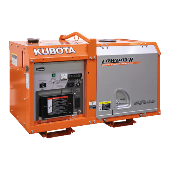
Kubota GL6000-AUS Operator's Manual
Diesel generator
Hide thumbs
Also See for GL6000-AUS:
- Operator's manual (62 pages) ,
- Operator's manual (63 pages) ,
- Operator's manual (49 pages)

Related Manuals for Kubota GL6000-AUS


Summary of Contents for Kubota GL6000-AUS
- Page 1 GL6000-STD · GL6000-AUS GL7000-USA · GL7000-USA-TM · GL7000-STD GL9000-STD · GL9000-AUS GL11000-USA · GL11000-USA-TM · GL11000-STD D-2396 D-2397 G3102-8916-3...
- Page 2 WARNING WARNING To prevent electrical shock the following instruction must be followed. Before the generator can be connected to a building’s electrical system, a licensed electrician must install an isolation (transfer) switch in the building’s main fuse box. The switch is the connection point for generator power and allows selection of generator or main line power to the building.
- Page 3 FOREWORD You are now the proud owner of a KUBOTA Diesel Engine Generator. This generator is a product of KUBOTA quality engineering and manufacturing. It is made of fine materials and under a rigid quality control system with correct maintenance. It will give you long, satisfactory service. To obtain the best use of your generator, please read this manual carefully.
-
Page 4: Table Of Contents
CONTENTS SAFETY PRECAUTIONS ..................1 SERVICING OF GENERATOR ................. 1 SPECIFICATION ....................... 2 NOMENCLATURE..................... 4 GROUND FAULT CIRCUIT INTERRUPTER (GFCI) RECEPTACLE ....... 8 PREPARATION TO SUPPLY THE ELECTRIC POWER ........10 CONNECTING THE LOAD..................12 PRE-OPERATION CHECK..................16 OPERATING THE GENERATOR................19 SERVICE INTERVALS .................... - Page 5 SAFETY PRECAUTIONS SAFETY PRECAUTIONS A To operate the machine safely, be sure to follow the instructions below. DANGER To avoid personal injury: A Hazard of being caught up in the machine: Do not touch any rotating parts. A Do not use or charge the battery if its fluid level stands below the LOWER mark.
- Page 6 SAFETY PRECAUTIONS CAUTION To avoid personal injury: A Electric shock and fire hazard: Do not connect the machine to any indoor (commercial) power outlet. A Electric shock and injury hazard: Do not allow children to run the machine. A Electric shock and injury hazard: Turn off the circuit breaker before starting the machine.
- Page 7 SAFETY PRECAUTIONS CAUTION To avoid personal injury: A Anti-freeze contains poison. Wear rubber gloves to avoid personal injury. In case of contact with skin, wash it off immediately. A DO NOT mix different types of Anti-freeze. The mixture can produce chemical reaction causing harmful substances.
- Page 8 SAFETY PRECAUTIONS CAUTION To avoid personal injury: A When checking engine or servicing, place the engine on a wide and level ground. DO NOT work on anything that is supported ONLY by lift jacks or a hoist. Always use blocks or correct stands to support the engine before servicing.
- Page 9 DANGER, WARNING AND CAUTION LABELS Pay special attention to all labels on the generator. Refer to following representations for labels used on the GL Series Generator. Labels are avail- able individually from your KUBOTA Dealer. (1) Part No. G3907-8832-0 (2) Part No. G3907-8830-0 (3) Part No.
- Page 10 SAFETY PRECAUTIONS (7) Part No. 18620-8806-0 (8) Part No. G3907-8833-0 (9) Part No. G3102-8841-0 (10) Part No. G3101-8832-0 (11) Part No. 6C040-5559-0 (12) Part No. G3102-8806-0 (13) Part No. G3906-8831-0 (14) Part No. G3102-8838-0 (for U.S.A.) (15) Part No. G3102-8839-0 (for U.S.A.)
- Page 11 2. Clean danger, warning and caution labels with soap and water, dry with a soft cloth. 3. Replace damaged or missing danger, warning and caution labels with new labels from your local KUBOTA Dealer. 4. If a component with danger, warning and caution label(s) affixed is replaced with new part, make sure new label(s) is (are) attached in the same location(s) as the replaced component.
-
Page 13: Safety Precautions
However, when in need of parts or major service, be sure to see your KUBOTA Dealer. For service, contact the KUBOTA Dealership from which you purchased your generator or your local KUBOTA Dealer. -
Page 14: Specification
SPECIFICATION SPECIFICATION GENERATOR GL6000 GL7000 Model Unit –STD –AUS –USA –USA-TM –STD Design — Salient-pole, revolving-field AC generator (AVR system with separate and self-excitation brush) Frequency Rated Output (COP) Rated Voltage 120/240 110/220 Rated amperage 22.9 54.2/27.1 59.1/29.5 Phase & Wire ø-W Power Factor No. - Page 15 SPECIFICATION GENERATOR GL9000 GL11000 Model Unit –STD –AUS –USA –USA-TM –STD Design — Salient-pole, revolving-field AC generator (AVR system with separate and self-excitation brush) Frequency Rated Output (COP) Rated Voltage 120/240 110/220 Rated amperage 36.4 33.3 83.3/41.7 90.9/45.5 Phase & Wire ø-W Power Factor No.
-
Page 16: Nomenclature
NOMENCLATURE NOMENCLATURE (1) Door (14) Oil filter cartridge (2) Coolant filling port (15) Muffler (3) Hook (16) Radiator (4) Fuel tank cap (17) Radiator cap (5) Fuel gauge (18) Solenoid (6) Control panel (19) Engine oil port (7) Base (20) Battery (8) Engine oil drain plug (21) Air cleaner (9) Door lock... - Page 17 NOMENCLATURE B Control Panel Standard Model C 1 Phase Type (120/240V Dual voltage Type) [GL11000-USA] [GL7000-USA] (1) A.C. Voltmeter (A) Receptacle (2) Glow timer lamp (B) Receptacle (3) Water temperature lamp (C) Receptacle (4) Oil pressure lamp (D) Receptacle (5) Battery charge lamp (6) Starter switch (key) (7) Circuit breaker (8) Hour meter...
- Page 18 NOMENCLATURE C 1 Phase Type C 1 Phase Type (120V/240V Dual voltage type) (110V/220V Dual voltage type) [GL11000-USA-TM] [GL11000-STD] [GL7000-USA-TM] [GL7000-STD] (1) A.C. Voltmeter (A) Receptacle (2) Glow timer lamp (3) Water temperature lamp (4) Oil pressure lamp (5) Battery charge lamp (6) Starter switch (key) (7) Circuit breaker (8) Hour meter...
- Page 19 NOMENCLATURE AUS Model C 1 Phase Type (220V Type) C 1 Phase Type (240V Type) [GL9000-STD] [GL9000-AUS] [GL6000-STD] [GL6000-AUS] (1) A.C. Voltmeter (A) Receptacle (2) Glow timer lamp (1) A.C. Voltmeter (A) Receptacles (3) Water temperature lamp (2) Glow timer lamp...
-
Page 20: Ground Fault Circuit Interrupter (Gfci) Receptacle
If the GFCI can not be reset, the GFCI is faulty. (1) Charge warning lamp Contact your KUBOTA dealer. If the GFCI resets (2) Water temperature-overheat warning lamp, flashes on when cooling water rises to 112° to 118°C. - Page 21 GROUND FAULT CIRCUIT INTERRUPTER (GFCI) RECEPTACLE B Control Box (1) Emergency unit (2) Regulator (3) Glow relay (4) Relay A (5) Relay B (6) Glow lamp timer (7) Starter relay (8) Exterior connection terminal taps (9) Separate excitation unit...
-
Page 22: Preparation To Supply The Electric Power
PREPARATION TO SUPPLY THE ELECTRIC POWER PREPARATION TO SUPPLY THE ELECTRIC POWER 1. Generator grounding 2. Recommended capacity of electrical The end user, equipment owner or operator must devices contact his local, state, county or municipal electric code department to determine the approved generator APPLICATION RANGE grounding method to be used in his application or You can operate the GL-series generator in the... - Page 23 PREPARATION TO SUPPLY THE ELECTRIC POWER A Connecting a motor. When starting the motor, the voltage drops immediately. The circuit may be opened if an electromagnetic switch is connected to the same circuit. When connecting two motors or more, make sure the total current capacity of the motors does not exceed the total rated current.
-
Page 24: Connecting The Load
CONNECTING THE LOAD CONNECTING THE LOAD B Connection Notes 1. Turn OFF the circuit breaker on the control panel. 2. Connect the load to the A.C. output terminals. 3. Be sure to close the terminal cover after connecting the load. WARNING To avoid personal injury: A Before... - Page 25 CONNECTING THE LOAD C Single phase 2 terminals type i) GL6000-STD, GL9000-STD 50Hz 220V (1) Light (2) Television (3) Air conditioner (4) Electric drill (1) Light (5) Motor pump (2) Television (3) Air conditioner C Single phase 3 terminals type (1P3W type) (4) Electric drill (Dual voltage type) (5) Motor pump...
- Page 26 CONNECTING THE LOAD C Single phase 3 terminals type (1P4W type) C Single phase 3 terminals type (1P3W type) (Dual voltage type) (Dual voltage type) i) GL7000-USA-TM i) GL11000-USA-TM 60Hz 120V 60Hz 120/240V ii) GL7000-USA-TM 60Hz 120/240V WARNING To avoid personal injury: A Do not switch the voltage selector with generator on.
- Page 27 A Connect or disconnect the load to engine is stopped. the AC receptacle only when the engine is stopped. i) GL9000-AUS 50Hz 240V ii) GL6000-AUS i) GL11000-USA 50Hz 240V 60Hz 120/240V ii) GL7000-USA 1. Turn OFF the circuit breakers on the control panel.
-
Page 28: Pre-Operation Check
PRE-OPERATION CHECK PRE-OPERATION CHECK B How to open the Door C Check items -Check for oil and coolant leakage -Check cooling air inlet and outlet for obstructions or clogging CAUTION -Check radiator fins for clogging To avoid personal injury from contact -Check fan belt tension -Check engine oil level with moving parts;... - Page 29 PRE-OPERATION CHECK Immediately, add distilled water C Engine oil The generator has been shipped without engine oil. until the battery's fluid level comes Fill with oil to the correct level before attempting to somewhere between the UPPER and start the engine. LOWER levels.
- Page 30 PRE-OPERATION CHECK C Fuel WARNING To avoid personal injury: A DO NOT refuel when engine is running or hot. A Always shut off the engine before refueling. A DO NOT overfill fuel system. If any fuel overflows, wipe it up completely before starting operation.
-
Page 31: Operating The Generator
OPERATING THE GENERATOR OPERATING THE GENERATOR CAUTION To avoid personal injury: A Read " SAFETY PRECAUTIONS" in the front of this manual. A Read the danger, warning and caution labels located generator. A To avoid the danger of exhaust fume poisoning, do not operate the engine in a closed building without proper ventilation. - Page 32 OPERATING THE GENERATOR 3. Ensure that the fuel lever is set to the 7. Turn the key to the "START" position "OPEN" Position. and release when the engine starts. (1) Fuel lever (A) "OPEN" (1) Starter switch (Key) (A) "OFF" (2) Fuel filter pot (B) "ON"...
- Page 33 OPERATING THE GENERATOR B Cold Weather Starting C Warm-up in cold ambient temperatures In cold weather, the engine oil may be cold with in- If the ambient temperature is below * -5°C (23°F) and creased viscosity. This can delay oil circulation or ab- the engine is very cold, start it in the following manner: normally low oil pressure for some time after engine Take steps (1) through (5) in "STARTING THE EN-...
- Page 34 OPERATING THE GENERATOR B Stopping the Engine B If the Engine Fails to Stop in the Usual Procedure (EMERGENCY STOP) 1. Turn OFF all electrical device switches If the engine does not stop after turning the key switch for connected loads. to "OFF"...
-
Page 35: Service Intervals
*4 Replace earlier if necessary. A The items listed above (@ marked) are registered as emission related critical parts by KUBOTA in the U.S. EPA non-road emission regulation. As the engine owner, you are responsible for the performance of the required maintenance on the engine according to the above instruction. - Page 36 SERVICE INTERVALS For North American market C Engine Oil: A Oil used in the engine should have an American Petroleum Institute (API) service classification and Proper SAE Engine Oil according to the ambient temperatures as shown P27. A Refer to the following table for the suitable API classification engine oil according to and the fuel. Fuel used Engine oil classification (API classification) Ultra Low Sulfur Fuel [<0.0015% (15 ppm)]...
-
Page 37: Periodic Service
PERIODIC SERVICE PERIODIC SERVICE B Fuel C Fuel level check and refueling 1. Check to see that the fuel level is above the lower Fuel is flammable and can be dangerous. You should limit of the fuel level gauge. handle fuel with care. 2. - Page 38 PERIODIC SERVICE Fuel tank capacity L (U.S.gal.) C Checking the fuel pipes Model Capacity CAUTION GL6000, GL7000 [Engine model : Z482] To avoid personal injury: 28 (7.4) GL9000, GL11000 A Check or replace the fuel pipes after [Engine model : D722] stopping the engine.
- Page 39 PERIODIC SERVICE C Cleaning the fuel filter pot Every 100 hours of operation, clean the fuel filter in a A Do not operate a diesel engine when engine oil is clean place to prevent dust intrusion. overfilled. This can effect the air intake system which could result in engine damage or malfunction.
- Page 40 PERIODIC SERVICE A When using oil of different brands from the previous C Replacing the Oil Filter Cartridge one, be sure to drain all the previous oil before adding the new engine oil. CAUTION C Changing Engine Oil To avoid personal injury: A Be sure to stop the engine before CAUTION changing the oil filter cartridge.
- Page 41 PERIODIC SERVICE B Air Cleaner CAUTION To avoid personal injury: A Be sure to stop the engine before cleaning air filter element. A Make sure hooking clip is tight enough. If it is loose, dust and dirt may be sucked into the engine, causing excessive wear or premature engine failure and need for engine repair.
- Page 42 PERIODIC SERVICE B Radiator A If the dust cup is mounted incorrectly, dust or dirt will Make it a rule to check the coolant level before every op- not collect in the cup and allow the dust to come into eration.
- Page 43 (3) Coolant drain plug (Engine) A If the radiator cap has to be removed, proceed with caution and securely retighten the cap. A If coolant is leaking, consult your local KUBOTA Dealer. A Make sure that muddy or sea water is not used in the radiator.
- Page 44 KUBOTA engines. 1. Check to see if the coolant runs short or if there is Contact KUBOTA concerning coolant for extreme any coolant leak; conditions. 2. Check to see if there is any obstacle around the 1.
- Page 45 If mixed with the cleaning agent, sludge may until the battery’s fluid level comes build up, adversely affecting the engine parts. 7. Kubota's genuine long-life coolant has a service life somewhere between the UPPER and of 2 years. Be sure to change the coolant every 2 LOWER levels.
- Page 46 PERIODIC SERVICE 1. Make sure that each electrolyte level is to the bottom of vent wells, if necessary, add only distilled water in a well-ventilated place. (1) Thick cable red (A) "HIGHEST LEVEL" (2) Battery case (B) "LOWEST LEVEL" (3) Negative / ground cable black (4) Plug (1) Battery electrolyte level (A) "TOO LOW"...
- Page 47 Failure to follow this procedure may result in serious damage to the generator electrical system. Refer to the troubleshooting section of this manual or your local KUBOTA Dealer for specific information.
- Page 48 PERIODIC SERVICE [Engine model ··· Z482, D722] (1) Fan belt (A) 12 to 14 mm (0.47 to 0.55 in.) (2) Bolt and adjust nut (under load of 98 N (22.1 lbs.)) (1) Fuse 3A : External connection terminal block (3) Lock nut (2) Fuse 10A : AC (Accessory Line) (3) Fuse 5A : Glow (4) Fuse 15A : Solenoid...
-
Page 49: Transporting / Storage
TRANSPORTING / STORAGE TRANSPORTING / STORAGE B Transporting B Storage CAUTION CAUTION To avoid personal injury: To avoid personal injury: A Secure the generator to prevent A DO NOT clean the machine with movement during operation. engine running. A DO NOT stand near or under the A To avoid the danger of exhaust fume generator while it is suspended. -
Page 50: Troubleshooting
TROUBLESHOOTING TROUBLESHOOTING CAUTION To avoid personal injury: A Always perform any check at "STOP" condition except for special check in which operation is required. A Do not touch the charging section during operation. A Keep your hands and body away from the rotating parts during operation. If the machine does not function properly, use the following chart to identify and correct the cause. - Page 51 • Remove oil to upper limit of gauge. Engine oil is over filled. • Replace fuel with good quality fuel. Fuel quality is bad. Abnormal sound Crack of vibration-proof rubber. • Replace. Large vibration. Others. • Check, repair. If you have any questions, contact your KUBOTA dealer.
-
Page 52: Automatic Start/Stop Unit (A S/S Unit)
AUTOMATIC START/STOP UNIT (A S/S UNIT) AUTOMATIC START/STOP UNIT (A S/S UNIT) To connect the machine to the A S/S UNIT the genera- tor is equipped with the ectt on the left side panel of the control panel. To connect the exterior apparatus with the machine, perform the following instructions;... -
Page 53: Wiring Diagram
WIRING DIAGRAM WIRING DIAGRAM... - Page 54 WIRING DIAGRAM...
- Page 55 WIRING DIAGRAM...
- Page 56 WIRING DIAGRAM...
- Page 57 WIRING DIAGRAM...
- Page 58 WIRING DIAGRAM...
- Page 59 WIRING DIAGRAM...
- Page 60 WIRING DIAGRAM...
- Page 61 WIRING DIAGRAM...
- Page 62 WIRING DIAGRAM...
Need help?
Do you have a question about the GL6000-AUS and is the answer not in the manual?
Questions and answers