Table of Contents
Advertisement
Advertisement
Table of Contents

Related Manuals for Kubota J106-STD


Summary of Contents for Kubota J106-STD
- Page 1 G3907-8911-5...
- Page 2 WARNING To prevent electrical shock the following instruction must be followed. Before the generator can be connected to a building’s electrical system, a licensed electrician must install an isolation (transfer) switch in the building’s main fuse box. The switch is the connection point for generator power and allows selection of generator or main line power to the building.
-
Page 3: Safety First
FOREWORD You are now the proud owner of a KUBOTA Diesel Engine Generator. This gen- erator is a product of KUBOTA quality engineering and manufacturing. It is made of fine materials and under a rigid quality control system with correct maintenance. -
Page 5: Table Of Contents
CONTENTS SAFE OPERATION ....................1 SERVICING OF GENERATOR..................1 SPECIFICATIONS .......................2 1 Phase Type ........................2 3 Phase Type ........................5 NOMENCLATURE .......................8 Control Panel........................10 Easy Checker ......................... 13 Control Box........................13 PREPARATION TO SUPPLY THE ELECTRIC POWER...........14 CONNECTING THE LOAD ..................16 Connection Notes...................... - Page 6 CONTENTS Changing Coolant......................37 Remedies for quick decrease of coolant ................ 37 Checking Radiator Hoses and Clamps ................38 Precaution Overheating....................38 Cleaning Radiator Core (outside)................... 38 Cleaning the Radiator..................... 38 Anti-freeze ........................38 BATTERY .......................39 Battery Charging ......................39 Instructions for Long Term Storage................
- Page 7 SAFE OPERATION SAFE OPERATION Careful operation is your best insurance against an accident. Read and understand this operator’s manual carefully before operating the generator. All operators, no matter how much experience they may have had, should read this manual and all labels on the generator before operating the generator.
- Page 8 SAFE OPERATION CHECK BEFORE OPERATION & STARTING THE ENGINE A Always turn off the circuit breaker and all switches for the electrical devices before starting the generator. A Check the wiring and connections of the electrical devices before starting the generator. A Be sure to check the engine before operation.
- Page 9 SAFE OPERATION KEEP THE AREA AROUND THE ENGINE CLEAN A Be sure to stop the engine before cleaning. A Keep the engine clean and free of accumulated dirt, grease and trash to avoid a fire. Store flammable fluids away from sparks and fire. A DO NOT stop the engine without idling.
- Page 10 SAFE OPERATION EXHAUST GASES & FIRE PREVENTION A Engine exhaust fumes can be very harmful if allowing them to accumulate. Be sure to run the engine in a well ventilated place and where there are no people or livestock near the generator. A DO NOT operate the generator in a closed area such as inside houses, warehouses, tunnels, wells, ship holds, tanks, etc.
- Page 11 SAFE OPERATION ESCAPING FLUID A Relieve all pressure in the oil and the cooling systems before any lines, fittings or related items are removed or disconnected. A Be alert for possible pressure when disconnecting any device from a system that utilizes pressure. DO NOT check for pressure leaks with your hand.
- Page 12 SAFE OPERATION CAUTIONS AGAINST BURNS & BATTERY EXPLOSION A To avoid burns, be alert for hot components, e.g. muffler, muffler cover, radiator, pipes, hoses, engine body, coolant, engine oil, etc. during operation and just after the engine has been shut off. A DO NOT remove the radiator cap while the engine is running or immediately after stopping.
- Page 13 SAFE OPERATION CONDUCTING SAFETY CHECKS & MAINTENANCE A Know how to stop the generator quickly, and understand operation of all the controls. DO NOT permit anyone to operate the generator without proper instruction. A When checking engine or servicing, place the generator in an open area and level ground.
- Page 14 DANGER, WARNING AND CAUTION LABELS Pay special attention to all labels on the generator. Refer to following representations for labels used on the J-Series Generator. Labels are available individually from your KUBOTA Dealer. (1) Part No. G3907-8832-0 (2) Part No. G3907-8830-0 (3) Part No.
- Page 15 SAFE OPERATION (7) Part No. 18620-8806-0 (8) Part No. G3907-8833-0 For the Z482 or D722-mounted machines only.
- Page 16 2. Clean danger, warning and caution labels with soap and water, dry with a soft cloth. 3. Replace damaged or missing danger, warning and caution labels with new labels from your local KUBOTA Dealer. 4. If a component with danger, warning and caution label(s) affixed is replaced with new part, make sure new label(s) is (are) attached in the same location(s) as the replaced component.
-
Page 17: Safe Operation
However, when in need of parts or major service, be sure to see your KUBOTA Dealer. For service, contact the KUBOTA Dealership from which you purchased your generator or your local KUBOTA Dealer. -
Page 18: Specifications
SPECIFICATIONS SPECIFICATIONS MOKUJIYOU B1 Phase Type GENERATOR J106 J107 J108 Model Unit -STD -AUS -STD -STD -AUS Salient-pole, revolving-field AC generator Design (AVR system with separate and self-excitation brush) Frequency Rated Output (COP) Rated Voltage 110/220 127/220 Phase & Wire φ-w Power Factor No. - Page 19 SPECIFICATIONS GENERATOR J110 J112 J114 Model Unit -STD -STD -AUS -STD Salient-pole, revolving-field AC generator Design (AVR system with separate and self-excitation brush) Frequency 11.5/ 14.0 Rated Output (COP) 11.5/ 14.0 Rated Voltage 110/220 127/220 110/220 127/220 Phase & Wire φ-w Power Factor No.
- Page 20 SPECIFICATIONS GENERATOR J116 J119 Model Unit -STD -AUS -STD Salient-pole, revolving-field AC generator Design (AVR system with separate and self-excitation brush) Frequency 18.8 11.5/18.8 Rated Output (COP) 18.8 11.5/18.8 Rated Voltage 110/220 127/220 Phase & Wire φ-w Power Factor No. of Poles Insulation Rotary coil: Class F, Stator coil: Class B Voltage Regulation...
-
Page 21: Phase Type
SPECIFICATIONS B3 Phase Type GENERATOR J310 J313 Model Unit -STD -AUS -STD Salient-pole, revolving-field AC generator Design (AVR system with separate and self-excitation brush) Frequency 12.5 Rated Output (COP) Rated Voltage Phase & Wire φ-w Power Factor No. of Poles Insulation Rotary coil: Class F, Stator coil: Class B Voltage Regulation... - Page 22 SPECIFICATIONS GENERATOR J315 J318 Model Unit -STD -AUS -STD Salient-pole, revolving-field AC generator Design (AVR system with separate and self-excitation brush) Frequency 17.5 Rated Output (COP) Rated Voltage Phase & Wire φ-w Power Factor No. of Poles Insulation Rotary coil: Class F, Stator coil: Class B Voltage Regulation 8 (No load to full load) Type of Coupling...
- Page 23 SPECIFICATIONS GENERATOR J320 J324 Model Unit -STD -AUS -STD Salient-pole, revolving-field AC generator Design (AVR system with separate and self-excitation brush) Frequency 10.8 23.5 Rated Output (COP) 10.8 18.8 Rated Voltage Phase & Wire φ-w Power Factor No. of Poles Insulation Rotary coil: Class F, Stator coil: Class B Voltage Regulation...
-
Page 24: Nomenclature
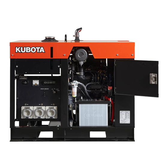
NOMENCLATURE NOMENCLATURE MOKUJIYOU (1) Control panel (2) Hook (3) Coolant filling port (4) Fuel tank cap (5) Door (6) Engine oil drain plug (7) Air cleaner (8) Battery (9) Reserve tank (10) Fuel cock (11) Engine oil port (12) Oil dipstick (13) Oil filter cartridge (14) Radiator (15) Coolant drain plug (radiator) - Page 25 NOMENCLATURE (1) Control panel (2) Hook (3) Coolant filling port (4) Fuel tank cap (5) Door (6) Engine oil drain plug (7) Air cleaner (8) Battery (9) Reserve tank (10) Fuel cock (11) Engine oil port (12) Oil dipstick (13) Oil filter cartridge (14) Radiator (15) Coolant drain plug (radiator) (16) Coolant drain plug (engine)
-
Page 26: Control Panel
NOMENCLATURE C 1 Phase Type (110V/220V Dual voltage type) BControl Panel [J107-STD, J110-STD] Standard Model C 1 Phase Type (220V Type) [J106-STD, J108-STD] [J114-STD, J119-STD] [J112-STD, J116-STD] (1) A.C. Voltmeter (7) Circuit breaker (2) Glow plug lamp (8) Hour meter... - Page 27 NOMENCLATURE C 1 Phase Type (127V/220V Dual voltage type) C 3 Phase Type [J107-SA, J110-SA] [J310-STD, J313-STD] [J114-SA, J119-SA] [J315-STD, J318-STD, J320-STD, J324-STD] (1) A.C. Voltmeter (7) Circuit breaker (1) A.C. Voltmeter (7) Circuit breaker (2) Glow plug lamp (8) Hour meter (2) Glow plug lamp (8) Hour meter (3) Water temperature lamp...
- Page 28 NOMENCLATURE AUS Model C 3 Phase Type [J310-AUS] C 1 Phase Type [J106-AUS, J108-AUS] [J315-AUS, J320-AUS] [J112-AUS, J116-AUS] (1) A.C. Voltmeter (7) Circuit breaker (2) Glow plug lamp (8) Hour meter (3) Water temperature lamp (9) Ground terminal The J106-AUS is equipped with 2 receptacles. (4) Oil pressure lamp (10) Terminal (Autostart unit) (1) A.C.
-
Page 29: Easy Checker
NOMENCLATURE BEasy Checker BControl Box When an abnormal condition occurs with a part monitored by the easy checker while the engine is running, a lamp flashes to warn the operator of the impending trouble. (1) Charge warning lamp (2) Water temperature-overheat warning lamp, flashes on when cooling water rises to 112 to 118 C. -
Page 30: Preparation To Supply The Electric Power
PREPARATION TO SUPPLY THE ELECTRIC POWER PREPARATION TO SUPPLY THE ELECTRIC POWER 1. Generator grounding The end user, equipment owner or operator must contact his local, state, county or municipal electric code department to determine the approved generator grounding method to be used in his application or location. - Page 31 PREPARATION TO SUPPLY THE ELECTRIC POWER 2. Recommended capacity of electrical A Connecting a motor. When connecting to a line starting motor, these devices generators may be used to start a submerged pump of 3.7kW, 5.5kW, 7.5kW (three phase). When starting APPLICATION RANGE the motor, the voltage drops immediately.
-
Page 32: Connecting The Load
(3) Cover lock bolt the main power line (backfeeding) when the main power supply has C Single phase 2 terminals type i ) J106-STD, J108-STD, J112-STD, J116-STD failed or has been turned off for line 50Hz 220V repair. Backfeeding can electrocute [Single phase] or injure line maintenance personnel. - Page 33 CONNECTING THE LOAD C Single phase 3 terminals type (1P3W type) C 3 phase and single phase 4 terminals type (Dual voltage type) A For 3 phase power source i ) J107-STD, J110-STD i ) J310-STD, J315-STD, J320-STD 60Hz 110/220V 50Hz 380V Use (W)-(V)-(U) ii) J107-SA, J110-SA, J114-SA, J119-SA...
-
Page 34: Connecting The Load (Aus Model)
CONNECTING THE LOAD A For single phase power source 2. Connect the load to the A.C. receptacles. i ) J310-STD, J315-STD, J320-STD [ A list of receptacles ] 50Hz 380V single phase Use (U)-(V), (V)-(W), (W)-(U) ii) J313-STD, J318-STD, J324-STD Single Phase 3 Phase 60Hz 220V single phase Use (U)-(V), (V)-(W), (W)-(U) -
Page 35: Handling The Circuit Breaker
HANDLING THE CIRCUIT BREAKER HANDLING THE CIRCUIT BREAKER MOKUJIYOU C Single phase (3 terminals - Dual voltage type) BHandling the Circuit Breaker (Protector) Panel control is designed to have the two A.C. circuit breaker. (Australian model) Turn ON the same voltage number circuit breaker as Each of the receptacles is provided with an over-current using the A.C. -
Page 36: Pre-Operation Check
PRE-OPERATION CHECK PRE-OPERATION CHECK DAILY CHECK To prevent problems from occurring, it is important to To avoid the possibility of battery know the condition of the generator. Always perform the explosion: following check items before starting the generator. The battery comes in two types: refillable and non-refillable. -
Page 37: Engine Oil
PRE-OPERATION CHECK A The duration of dry charged efficiency, will decrease in BFuel proportion to the period of time elapsed after shipment and during storage. To obtain the longest service life of the battery, it is necessary for the battery to be To avoid personal injury: charged for a sufficient period of time. -
Page 38: Operating The Generator
OPERATING THE GENERATOR OPERATING THE GENERATOR MOKUJIYOU BStarting the Engine 1. Turn off all switches on the electrical To avoid personal injury: devices. A Read " SAFE OPERATION" in the front of this manual. 2. Turn off the circuit breakers on the A Read danger, warning... - Page 39 OPERATING THE GENERATOR 3. Ensure that the fuel lever is set to the 6. Turn the key to "GLOW" position. "OPEN" Position. A See "Cold Weather Starting" section as to the preheating times. 7. Turn the key to the "START" position and release when the engine starts.
-
Page 40: Cold Weather Starting
OPERATING THE GENERATOR C Warm-up in cold ambient temperatures In cold weather, the engine oil may be cold with increased BCold Weather Starting viscosity. This can delay oil circulation or abnormally low If the ambient temperature is below * -5 C (23 F) and the oil pressure for some time after engine start-up. -
Page 41: Stopping The Engine
OPERATING THE GENERATOR BStopping the Engine BIf the Engine Fails to Stop in the Usual Procedure (EMERGENCY STOP) 1. Turn OFF all electrical device switches for connected loads. If the engine does not stop after turning the key switch to "OFF"... - Page 42 OPERATING THE GENERATOR 3. After stopping the engine, make sure that the door is closed and the main switch (key) is at "OFF". 4. The following causes are possible for such unusual engine shut-off. Pinpoint and correct the cause of trouble. A Check for the stop solenoid.
-
Page 43: Maintenance
*2 Generator carbon brush should be checked more often in dusty conditions than in normal conditions. *3 After 6 times of cleaning. *4 Consult your local KUBOTA Dealer for this service. A When the battery is used for less than 100 hours in a year, check its electrolyte yearly. (for refillable battery’s only) - Page 44 *2 Generator carbon brush should be checked more often in dusty conditions than in normal conditions. *3 After 6 times of cleaning. *4 Consult your local KUBOTA Dealer for this service. A When the battery is used for less than 100 hours in a year, check its electrolyte yearly. (for refillable battery’s only)
-
Page 45: Periodic Service
PERIODIC SERVICE PERIODIC SERVICE FUEL BFuel Level Check and Refueling Fuel is flammable and can be dangerous. You should 1. Check to see that the fuel level is above the lower limit handle fuel with care. of the fuel level gauge. 2. -
Page 46: Air Bleeding The Fuel System
PERIODIC SERVICE No.2-D is a distillate fuel oil of lower volatility for engines in industrial and heavy mobile service. BAir Bleeding the Fuel System (SAE J313 JUN87) Grade of Diesel Fuel Oil According to ASTM D975 To avoid personal injury; A Do not bleed a hot engine as this could cause fuel to spill onto a hot exhaust manifold creating a danger... -
Page 47: Checking The Fuel Pipes
PERIODIC SERVICE BChecking the Fuel Pipes BCleaning the Fuel Filter Pot Every 100 hours of operation, clean the fuel filter in a clean place to prevent dust intrusion. To avoid personal injury: 1. Close the fuel filter lever. A Check or replace the fuel pipes after stopping the engine. -
Page 48: Engine Oil
PERIODIC SERVICE ENGINE OIL BChecking Oil Level and Adding Engine Oil 1. Check the engine oil level before starting or more than 5 minutes after stopping the engine. To avoid personal injury: 2. Remove the oil level gauge, wipe it clean and reinstall A Be sure to stop the engine before checking and changing the engine 3. -
Page 49: Changing Engine Oil
PERIODIC SERVICE 4. If the oil level is too low, remove the oil port, and add new oil to the prescribed level. BChanging Engine Oil 5. After adding oil, wait more than 5 minutes and check the oil level again. It takes some time for the oil to drain down to the oil pan. -
Page 50: Replacing The Oil Filter Cartridge
PERIODIC SERVICE 5. After the new cartridge has been replaced, the engine oil level normally decreases a little. Therefore run the BReplacing the Oil Filter Cartridge engine for a while and check for oil leaks through the seal before checking the engine oil level. Add oil if necessary. -
Page 51: Cleaning Primary Air Filter Element
PERIODIC SERVICE BCleaning Primary Air Filter Element 1. To clean the element, use clean dry compressed air on the inside of the element. Air pressure at the nozzle must not exceed 205 kPa (2.1 kgf/cm , 30 psi). Maintain reasonable distance between the nozzle and filter. -
Page 52: Radiator
PERIODIC SERVICE RADIATOR 2. If the radiator is provided with a reserve tank, check the coolant level of the reserve tank. When it is Make it a rule to check the coolant level before every between the "FULL" and "LOW" marks, the coolant operation. -
Page 53: Changing Coolant
3. Check the internal blockage in the radiator cooling A If coolant is leaking, consult your local KUBOTA tubes. If scale forms in the tubes, clean with the scale Dealer. inhibitor or its equivalent. -
Page 54: Checking Radiator Hoses And Clamps
10 minutes or while the steam water in KUBOTA engines. continues to blow out. Contact KUBOTA concerning coolant for extreme 5. Checking that there is no danger of being burned conditions. eliminate the causes of overheating according to the manual, see "TROUBLESHOOTING"... -
Page 55: Battery
If mixed with the cleaning agent, sludge may build up, A When the battery is being activated, adversely affecting the engine parts. 7. Kubota's genuine long-life coolant has a service life of hydrogen and oxygen gases in the 2 years. Be sure to change the coolant every 2 years. - Page 56 PERIODIC SERVICE 1. Make sure that each electrolyte level is to the bottom of vent wells, if necessary, add only distilled water in a well-ventilated place. (1) Battery electrolyte level (A) "TOO LOW" (B) "PROPER" (C) "TOO HIGH" 2. To slow charge the battery, connect the charger positive terminal to the battery positive terminal, and the negative to the negative, then recharge in the normal manner.
-
Page 57: Instructions For Long Term Storage
PERIODIC SERVICE 6. Clamp the other cable to the negative (black, (-) or neg.) terminal of the helper battery. BInstructions for Long Term Storage 7. Clamp the other end to the engine block or frame of 1. When storing the generator for long periods of time, the generator as far from the dead battery as possible. -
Page 58: Periodic Servicing And Cleaning Of The Generator
PERIODIC SERVICE PERIODIC SERVICING AND CLEANING OF 1. Loosen the three M6 x 12 mm lock screws of the cleaner cover, and take out the cleaner cover. THE GENERATOR To avoid personal injury: A Only a qualified electrical engineer must be allowed to do the servicing and cleaning. - Page 59 PERIODIC SERVICE (4) If the above allowance is shorter than 7 mm, 4. Checking and cleaning the couplers replace the carbon brush holder assembly with (1) There are three sets of couplers in total. new one. In replacing, be careful not to confuse (2) Disconnect all the couplers, and clean up the wire the colors of cords (3 and 4).
-
Page 60: Fuse
Refer “TROUBLESHOOTING“ section of this manual or your local KUBOTA Dealer for specific information. [J106, J107, J108, J110, J310, J313] [Engine model : Z482, D722] (1) Fuse 3A : External connection terminal block (2) Fuse 10A... -
Page 61: Fan Belt
PERIODIC SERVICE [J112, J114, J116, J119, J315, J318, J320, J324] [Engine model : Z482, D722] [Engine model : D1005, V1305] [Engine model : D1005, V1305] (1) Fuse 3A : External connection terminal block (2) Fuse 10A : AC (Accessory Line) (3) Fuse 5A : Glow (4) Fuse 5A... -
Page 62: Transporting / Storage
TRANSPORTING / STORAGE TRANSPORTING / STORAGE MOKUJIYOU BTransporting BStorage To avoid personal injury: To avoid personal injury: A Secure the generator to prevent A DO NOT clean the machine with movement during operation. engine running. A DO NOT stand near or under A To avoid the danger of exhaust fume generator while it is suspended. -
Page 63: Troubleshooting
TROUBLESHOOTING TROUBLESHOOTING MOKUJIYOU To avoid personal injury: A Always perform any check at ”STOP” condition except for special check in which operation is required. A Do not touch the charging section during operation. A Keep your hands and body away from the rotating parts during operation. If the machine does not function properly, use the following chart to identify and correct the cause. -
Page 64: Easy Checker
TROUBLESHOOTING BEasy Checker Trouble Cause Countermeasure When the key is turned, the Bulb is below or defective. Replace lamp doesn’t light on. Component or wiring defect of charging Check, repair circuit The water temperature lamp Engine overheating. See “Precaution Overheating“ in lights on when operating. - Page 65 Remove oil to upper limit of gauge. Fuel quality is bad. Replace fuel with good quality fuel. Abnormal sound Crack of vibration-proof rubber. Replace. Large vibration. Others. Check, repair. If you have any questions, contact your KUBOTA dealer. D1005, V1305 engine only...
-
Page 66: Automatic Start/Stop Unit (A S/S Unit)
AUTOMATIC START/STOP UNIT (A S/S UNIT) AUTOMATIC START/STOP UNIT (A S/S UNIT) To connect the machine to the A S/S UNIT the generator is equipped with the ECTT on the left side panel of the control panel. To connect the exterior apparatus with the machine, perform the following instructions;... -
Page 67: Wiring Diagram
WIRING DIAGRAM WIRING DIAGRAM... - Page 68 WIRING DIAGRAM...
- Page 69 WIRING DIAGRAM...
- Page 70 WIRING DIAGRAM...
- Page 71 WIRING DIAGRAM...
- Page 72 WIRING DIAGRAM...
- Page 73 WIRING DIAGRAM...
- Page 74 WIRING DIAGRAM...
- Page 75 WIRING DIAGRAM...
- Page 76 WIRING DIAGRAM...
- Page 77 WIRING DIAGRAM...
- Page 78 WIRING DIAGRAM...
- Page 79 WIRING DIAGRAM...
- Page 80 WIRING DIAGRAM...
- Page 81 WIRING DIAGRAM...
- Page 82 WIRING DIAGRAM...
- Page 83 WIRING DIAGRAM...
- Page 84 WIRING DIAGRAM...
- Page 85 WIRING DIAGRAM...
Need help?
Do you have a question about the J106-STD and is the answer not in the manual?
Questions and answers