Summarization of Contents
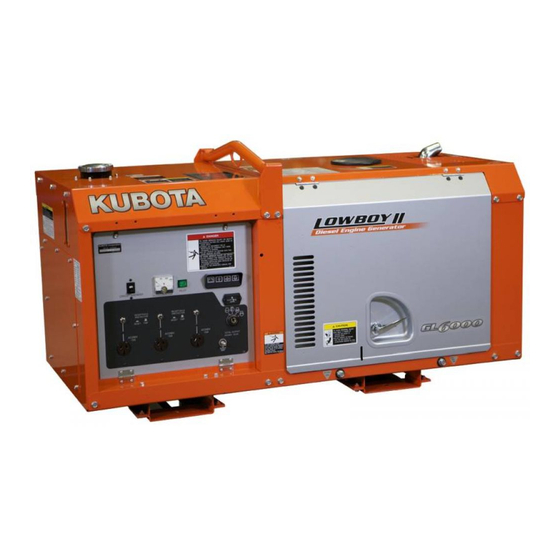
Kubota Diesel Generator Workshop Manual
Model Identification: GL6000, GL7000, GL9000, GL11000
Identifies the specific diesel generator models covered by the manual.
Manual Overview and Structure
Understanding the Manual Sections
Explains the manual is divided into General, Mechanism, and Servicing parts.
Essential Safety Instructions
Safety First: Symbols and Precautions
Details safety alert symbols and general precautions before servicing.
Safe Operating and Fire Prevention Guidelines
Covers safe starting, working practices, and avoiding fire hazards during operation.
Environmental and Emergency Preparedness
Outlines ventilation, fluid disposal, acid burn prevention, and emergency preparedness.
Generator Safety Decals
Location and Identification of Safety Decals
Illustrates safety decals installed on the generator and their meanings.
Generator Model Specifications
GL6000 Series Specifications
Provides detailed technical specifications for GL6000-STD and GL6000-AUS models.
GL7000 Series Specifications
Lists technical specifications for GL7000-USA, GL7000-USA-TM, and GL7000-STD models.
GL9000 Series Specifications
Details technical specifications for GL9000-STD and GL9000-AUS models.
GL11000 Series Specifications
Provides technical specifications for GL11000-USA, GL11000-USA-TM, and GL11000-STD models.
Generator Physical Dimensions
Dimensional Data for Generator Models
Presents length, width, and height specifications for different generator models.
General Information
Model and Serial Number Identification
Explains how to identify model and serial numbers for the engine and generator.
General Precautions
Service and Disassembly Precautions
Outlines important precautions for disassembly, reassembly, and part handling.
Electrical System Handling Precautions
Wiring and Connection Best Practices
Details correct methods for wiring, terminal tightening, and grommet insertion.
Battery and Fuse Handling Procedures
Covers precautions for battery connection, fuse usage, and connector separation.
Lubricants, Fuel, and Coolant Recommendations
Engine Oil, Fuel, and Coolant Specifications
Lists recommended lubricants, fuel types, and coolant for the generators.
Torque Specifications
General Use Screw, Bolt, and Nut Torques
Provides tightening torque values for common fasteners.
Special Use Screw, Bolt, and Nut Torques
Lists specific torque values for special application fasteners.
Maintenance Schedule
Generator Maintenance Check List by Interval
Presents a comprehensive list of maintenance checks based on operating hours or time intervals.
Regular Checks and Maintenance
Daily Engine Checks
Details daily checks for engine oil and coolant levels.
Initial 50-Hour Service Points
Outlines specific maintenance tasks required after the first 50 hours of operation.
Periodic Maintenance Checks
50-Hour Service Intervals
Covers checks for fuel lines and engine oil at 50-hour intervals.
100-Hour Service Intervals
Details maintenance tasks for the 100-hour service, including engine oil changes.
Engine Component Checks
800-Hour Valve Clearance Adjustment
Explains the procedure for checking and adjusting valve clearance at 800-hour intervals.
Special Tools Required for Servicing
Valve Seat Cutters and Compression Testers
Lists specialized tools for valve seat repair and engine compression testing.
Oil Pressure and Plastigauge Tools
Describes tools for measuring oil pressure and crankshaft bearing clearance.
Mechanism Overview
Engine Body Components
Describes the engine body, including the half-floating head cover.
Lubricating System Functionality
Explains the engine's lubricating system components and oil flow.
Cooling System Operation
Details the components and function of the engine's cooling system.
Fuel System Diagram
Illustrates the fuel tank, filter, and injection pump system.
Servicing Procedures
Troubleshooting Common Issues
Provides solutions for common engine and generator problems.
Servicing Specifications and Torque Values
Lists detailed specifications and tightening torques for engine components.
Cylinder Head and Valve Servicing
Cylinder Head Surface Flatness and Flaw Checks
Details procedures for checking cylinder head flatness and detecting cracks.
Valve Recessing and Stem/Guide Clearance
Explains how to measure and adjust valve recessing and stem-to-guide clearance.
Generator System
Generator Component Structure
Describes the main components of the generator assembly.
Automatic Voltage Regulator (AVR) Function
Explains the role and operation of the Automatic Voltage Regulator.
Emergency Relay Circuit Operation
Details the function of the automatic engine stopping device and its relays.
Generator Grounding Requirements
Provides instructions for proper grounding of the generator for safety.
Wiring Diagram Color Codes
Lists the color codes used for wiring in the generator's electrical system.
Generator Wiring Diagrams
GL6000-STD (220V-50Hz) Wiring
Provides the electrical schematic for the GL6000-STD model.
GL6000-AUS (240V-50Hz) Wiring
Presents the electrical schematic for the GL6000-AUS model.
GL7000 Series Wiring Diagrams
Includes electrical schematics for GL7000 models.
GL9000 Series Wiring Diagrams
Provides electrical schematics for GL9000 models.
GL11000 Series Wiring Diagrams
Includes electrical schematics for GL11000 models.
Generator Servicing and Troubleshooting
Generator Troubleshooting Guide
Lists common generator defects, causes, confirmations, and countermeasures.
Generator Servicing Specifications
Provides key electrical specifications for various generator models.
Generator Torque Specifications
Lists tightening torques for special screws and bolts used in generator assembly.
Control Panel Checks
Main Switch and Safety Switch Continuity Tests
Details procedures for testing main switch and safety switch continuity.
Lamp Timer and Regulator Checks
Explains how to test the glow plug lamp timer and regulator performance.
Circuit Breaker and Pilot Box Testing
Covers testing procedures for circuit breakers and pilot box lamps.
External Component Servicing
Control Panel and Generator Disassembly
Guides on disassembling external components like the control panel and generator assembly.
Rotor and Ball Bearing Replacement
Details the process for removing the rotor assembly and replacing ball bearings.
Generator Coil and Terminal Servicing
Terminal Voltage and Stator Coil Checks
Describes how to measure terminal voltages and test stator coil continuity.
Rotor Coil and Exciter Coil Servicing
Covers procedures for measuring resistance and grounding of rotor and exciter coils.


Need help?
Do you have a question about the GL7000 and is the answer not in the manual?
Questions and answers