
Related Manuals for Electro-Voice MTS


Summary of Contents for Electro-Voice MTS
- Page 1 MTS High Output Point Source MTS‑4153‑64 | MTS‑6154‑64 | MTS‑4153‑43 | MTS‑6154‑43 Installation manual...
-
Page 3: Table Of Contents
MTS High Output Point Source Table of contents | en Table of contents Important safety instructions Suspension Chlorine Precautions Copyright and disclaimer Personal Protective Equipment (PPE) Safety standards System overview Dimensions MTS-4153-64 standard dimensions MTS-6154-64 cardioid dimensions MTS-4153-43 standard dimensions... -
Page 4: Important Safety Instructions
It is the responsibility of the person installing the assembly to make sure the wall, ceiling, structure, and any attachments are capable of supporting all objects suspended overhead. Never modify Electro-Voice loudspeakers or rigging components or use a partial assembly of rigging components. -
Page 5: Chlorine
Chlorine Warning! Do not install MTS loudspeaker systems in high chlorine environments, such as swimming pools. Precautions These Electro-Voice loudspeakers were designed for use in an environment with ambient temperatures between -20°C (-4°F) and +50°C (122°F). -
Page 6: Safety Standards
| Important safety instructions MTS High Output Point Source Safety standards Bosch Security Systems Inc. LLC 130 Perinton Pkwy, Fairport, NY 14450 USA Confirms that this product has been designed and validated to meet or exceed the relevant sections of: –... -
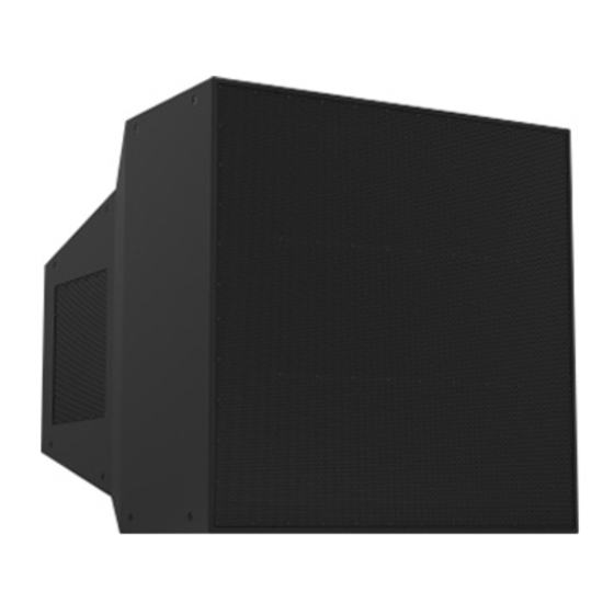
Page 7: System Overview
MTS loudspeakers are available in either white or black. Each loudspeaker has 24 M10 hard points for suspension in either horizontal or vertical configurations. -
Page 8: Dimensions
| Dimensions MTS High Output Point Source Dimensions MTS-4153-64 standard dimensions 134.0 5.28 1013.4 39.90 447.0 17.60 (PW VERSIONS) 337.113.27 1095.5 43.13 44.5 102.1 1.75 1051.0 41.38 1092.2 43.00 4.02 427.0 16.81 M10-1.5 THREADED HOLES (24 PLACES) (FW VERSIONS) 619.0 24.37... -
Page 9: Mts-6154-64 Cardioid Dimensions
MTS High Output Point Source Dimensions | en MTS-6154-64 cardioid dimensions 134.0 5.28 M10-1.5 THREADED HOLES 337.1 13.27 (32 PLACES) 1190.5 46.87 1092.2 43.00 102.1 4.02 44.5 1.75 279.7 11.01 742.4 29.23 1013.4 39.90 683.7 26.92 312.4 12.30 822.2 32.37... -
Page 10: Mts-4153-43 Standard Dimensions
| Dimensions MTS High Output Point Source MTS-4153-43 standard dimensions 134.0 5.28 1013.4 39.90 648.0 25.51 (FOR PW VERSIONS) 444.7 17.51 1491.0 58.70 43.7 1092.2 1.72 1447.3 56.98 43.00 99.7 3.92 627.0 M10-1.5 THREADED HOLES 24.69 (24 PLACES) (FOR FW VERSIONS) 576.0... -
Page 11: Mts-6154-43 Cardioid Dimensions
MTS High Output Point Source Dimensions | en MTS-6154-43 cardioid dimensions 134.0 5.28 444.7 M10-1.5 THREADED HOLES 17.51 (32 PLACES) 99.7 1493.8 58.81 44.5 1092.2 43.00 3.92 1.75 451.0 17.76 1013.4 39.90 884.8 856.7 33.73 34.83 464.8 18.30 VIEW A 814.2 32.05... -
Page 12: Wiring And Connections
(Phoenix Contact P/N 1709212). The connectors can accommodate up to 6 mm AWG) stranded wire. A cover plate with gland nuts is included with MTS. It provides protection for the speaker and wiring against water ingress. The cover plate must be installed for outdoor and full exposure applications. - Page 13 MTS High Output Point Source Wiring and connections | en Cardiod models with single amplifier Amplifier IPX 20:4 IPX 10:4 IPX 5:4 IPX 10:8 Total no. of speakers Channel (2 boxes) (2 boxes) (1 box) (1 box) (2 boxes) (2 boxes)
-
Page 14: Input Connections, Wiring Diagram And Schematic For Standard Models
| Wiring and connections MTS High Output Point Source Input connections, wiring diagram and schematic for standard models Figure 4.1: Input connections label for standard models STANDARD PARALLEL STANDARD DUAL (bi-amp configuration) (tri-amp configuration) AMP CHANNEL 1 AMP CHANNEL 1... - Page 15 MTS High Output Point Source Wiring and connections | en Electro-Voice 2021-09 | V01 | F.01U.386.524 Installation manual...
-
Page 16: Input Connections, Wiring Diagram And Schematic For Cardioid Models
| Wiring and connections MTS High Output Point Source Input connections, wiring diagram and schematic for cardioid models Figure 4.3: Input connections label for cardioid models CARDIOID PARALLEL CARDIOID PARALLEL (tri-amp configuration) (quad-amp configuration) AMP CHANNEL 1 AMP CHANNEL 1... - Page 17 MTS High Output Point Source Wiring and connections | en Electro-Voice 2021-09 | V01 | F.01U.386.524 Installation manual...
-
Page 18: Installing Weather Plate And Gland Nuts
| Wiring and connections MTS High Output Point Source Installing weather plate and gland nuts Remove (2) screws and the weatherproof plate from the input cup. Note the orientation of the plate since the screw holes are not symmetrical. - Page 19 MTS High Output Point Source Wiring and connections | en Connect the terminal blocks to the input connectors, and secure with the (4) captive screws. Pull the cable(s) through the gland nut(s) while you push the plate toward the input cup until it seats properly and is flush with the outer flange.
-
Page 20: Designing An Mts Array
You can also use EASE or EASE Focus to model acoustics. Mechanical design MTS-4153 models are equipped with 24 M10 external suspension points for connection of eyebolts or 3 party suspension hardware. MTS-6154 models are equipped with 32 M10 external suspension points for connection of eyebolts or 3 party suspension hardware. -
Page 21: M10 Suspension Points: Attachment At Any Angle
MTS High Output Point Source Designing an MTS array | en For fully weatherized (FW) models, always coat fasteners with RTV (silicon sealant) prior to insertion. Make sure a completely watertight seal is achieved and the threads are completely coated. - Page 22 | Designing an MTS array MTS High Output Point Source Warning! This is the maximum shear force for the hardpoints, not for the attached hardware (for example, steel frames). Always use attachment hardware with adequate strength and safety factor.
-
Page 23: Recommended Rigging Methods
Any hardware used to suspend a loudspeaker not provided by Electro-Voice is the responsibility of others. Notice! Electro-Voice has experienced and knowledgeable application engineers willing to assist with any design related questions. Contact information for technical support is located at www.electrovoice.com... -
Page 24: Single Loudspeaker Suspension Using M10 Eyebolts
Single loudspeaker suspension using M10 eyebolts Suspend MTS loudspeaker models individually using the M10 suspension points. MTS is a very heavy loudspeaker. A minimum of 4 points must be used to suspend the speaker, 2 points minimum per planar surface. - Page 25 MTS High Output Point Source Designing an MTS array | en DO NOT use a single pick point suspension system. Use multiple structural pick points or a single pick point with a secondary safety. See the examples that follow. Use a minimum of two pick points. This example uses three pick points.
- Page 26 | Designing an MTS array MTS High Output Point Source Always suspend MTS from the top of the enclosure, relative to its orientation. Speakers must not be suspended from cables attached to eye bolts on the sides of the cabinet.
-
Page 27: Custom Frame Design Considerations
Only certified structural engineers should be used to design any custom suspension frame. Failure to do so could result in serious injury or death. Warning! Any hardware used to suspend a loudspeaker array not associated with Electro-Voice is the responsibility of others. Warning! The simplified designs shown are for illustrative purposes only and do not represent or imply a complete design from Electro-Voice. - Page 28 | Designing an MTS array MTS High Output Point Source Correct Incorrect Use at least eight M10 structural hard points DO NOT use fewer than four M10 hard points on each loudspeaker element, four on each on each side of the loudspeaker.
- Page 29 MTS High Output Point Source Designing an MTS array | en Correct Incorrect Install lateral support bars after the DO NOT use plates on each side of the array loudspeakers are mounted to the frame sides without lateral support. to ensure they are tight to the loudspeakers, and that the frame is rigid between the side mounting points.
- Page 30 | Designing an MTS array MTS High Output Point Source Correct Incorrect The gap between the custom frame and the DO NOT allow any gap between the enclosure must be less than 1.5 mm (0.06 enclosure and the custom frame that exceeds in).
-
Page 31: Consideration For Weatherized Design
Drain holes The MTS fully weatherized models have optional drain holes on the bottom of the enclosure. The drain hole design discharges any water that accumulates over time. Electro-Voice recommends that the installer opens the drain holes for applications in which MTS loudspeakers will be directly exposed to precipitation. - Page 32 | Consideration for weatherized design MTS High Output Point Source 2021-09 | V01 | F.01U.386.524 Electro-Voice Installation manual...
- Page 34 Bosch Sicherheitssysteme GmbH Bosch Security Systems, LLC Robert-Bosch-Ring 5 12000 Portland Avenue South 85630 Grasbrunn Burnsville MN 55337 Germany www.boschsecurity.com www.electrovoice.com © Bosch Sicherheitssysteme GmbH, 2021 © Bosch Security Systems, LLC, 2021 202110151751...
Need help?
Do you have a question about the MTS and is the answer not in the manual?
Questions and answers