
Related Manuals for 3M 33573


Summary of Contents for 3M 33573
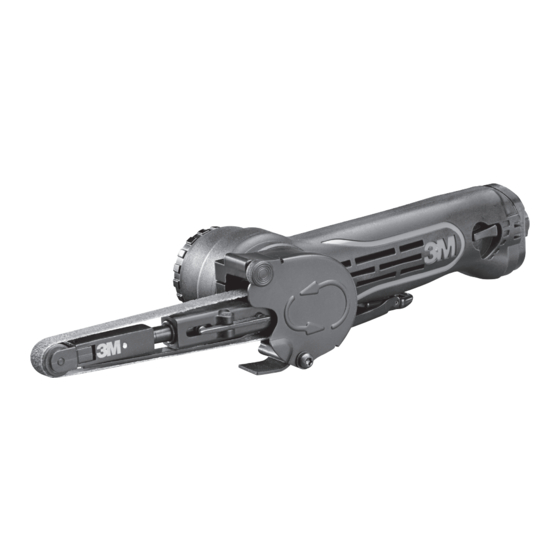
- Page 1 OPERATOR’S MANUAL & SAFETY INSTRUCTIONS 3M™ File Belt Sander PN 33573 330 mm (13 in.) 17,000 RPM PN 33575 457 mm (18 in.) 17,000 RPM 2017-02-21, Version 2 Translation of Original Instructions...
-
Page 2: Table Of Contents
3M LIMITED ONE YEAR WARRANTY . . . . . . . . . . . . . . . . . . -
Page 3: Important Safety Information
IMPORTANT SAFETY INFORMATION Please read, understand, and follow all safety information contained in these instructions prior to the use of this device . RETAIN THESE INSTRUCTIONS FOR FUTURE REFERENCE . Read the Safety Data Sheets (SDS) WARNING before using any materials. Exposure to DUST generated from workpiece and/or abrasive materials can result in lung damage and/or other physical injury. -
Page 4: Explanation Of Signal Word Consequences
EXPLANATION OF SIGNAL WORD CONSEQUENCES Indicates a potentially hazardous situation, which, if not avoided, could result in WARNING: death or serious injury and/or property damage . Indicates a potentially hazardous situation, which, if not avoided, may result in minor CAUTION: or moderate injury and/or property damage . -
Page 5: Warning
• Only use accessories supplied or recommended by 3M . • Use only with mounting hardware recommended by 3M; check with 3M for mounting hardware requirements . • Never allow this tool to be used by children or untrained people . -
Page 6: Caution
. The tool can also be used to remove gaskets and sealants . Only accessories specifically recommended by 3M should be used with this tool . Use in any other manner or with other accessories could lead to unsafe operating conditions . -
Page 7: Exploded Sander (Parts) View
EXPLODED SANDER (PARTS) VIEW PN 33573 (13 in.) AND PN 33575 (18 IN.) File Belt Sander PARTS LIST ITEM DESCRIPTION ITEM DESCRIPTION 18 in . Contact Arm Assembly- 10 mm Wheel Parallel Key 18 in . Contact Arm Assembly- 13 mm Wheel Rotor Blade 13 in . -
Page 8: Maintenance/Lubricating And Operating Instructions
. If such equipment is not used, the tool should be manually lubricated . To manually lubricate the tool, disconnect the airline and put two to three drops of 3M™ Air Lubricant PN 20451 (or equivalent 10 centistoke oil) into the air inlet of the tool . Reconnect tool to the air supply and run tool slowly for a few seconds to allow air to circulate the oil . - Page 9 • The tool RPM should be checked on a regular basis to ensure proper operating speed . • Make sure the tool is disconnected from the air supply and then attach 3M abrasive belt to the sander . Always wear required safety equipment when using this tool .
-
Page 10: To Install/Remove The Abrasive Belt
TO INSTALL/REMOVE THE ABRASIVE BELT Disconnect the tool from the air line . 2 . Hold the tool with the contact arm pointing downward . Push the contact arm against a hard surface to gain some slack until the safety latch (A) clicks into the locking position . 3 . -
Page 11: To Install/Remove The Contact Arms
TO INSTALL/REMOVE THE CONTACT ARMS Disconnect the tool from the air line . 2 . Hold the tool with the contact arm facing downward . Push the contact arm against a hard surface until the safety latch (A) clicks into the locking position . 3 . -
Page 12: To Install/Change The Contact Wheel
TO INSTALL/CHANGE THE CONTACT WHEEL Disconnect the tool from the air line . 2 . Hold the tool with the contact arm pointing downward . Push the contact arm against a hard surface to gain some slack until the safety latch (A) clicks into the locking position . Unfasten the set screw (B) . ( See Fig . 1) 3 . -
Page 13: Replacement Parts
REPLACEMENT PARTS CONTACT WHEEL REPLACEMENT KIT KIT DESCRIPTION PART NUMBER CONTENT 10 mm Contact Wheel Kit 33583 1 . 10 mm - Wheel Assembly 2 . Screw for 10 mm Wheel 13 mm Contact Wheel Kit 33584 1 . 13 mm –Wheel Assembly 2 . -
Page 14: Declaration Of Conformity
DECLARATION OF CONFORMITY Learn more about air sanders and polishers we have.
Need help?
Do you have a question about the 33573 and is the answer not in the manual?
Questions and answers