Table of Contents
Advertisement
Advertisement
Table of Contents

Subscribe to Our Youtube Channel
Related Manuals for ProForm TRAINER 8.7


Summary of Contents for ProForm TRAINER 8.7
-
Page 2: Table Of Contents
Note: The decals may not be shown at actual size. PROFORM and IFIT are registered trademarks of iFIT Inc. App store is a trademark of Apple Inc., registered in the U.S. and other countries. Android and Google Play are trademarks of Google LLC. The Bluetooth word mark ®... -
Page 3: Important Precautions
19. To purchase a surge suppressor, see your 6. Use the treadmill only as described in this local PROFORM dealer, see the front cover manual. of this manual, or see your local electronics store. - Page 4 19. Read, understand, and test the emergency 26. When folding or moving the treadmill, make stop procedure before using the treadmill sure that the storage latch is holding the (see HOW TO TURN ON THE CONSOLE on frame securely in the storage position. Do page 21).
- Page 5 STANDARD SERVICE PLANS...
-
Page 6: Before You Begin
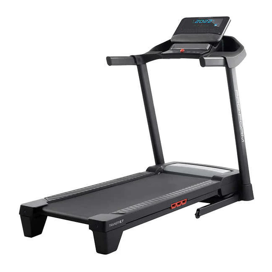
Thank you for selecting the new PROFORM reading this manual, please see the front cover of this ® TRAINER 8.7 treadmill. The TRAINER 8.7 treadmill manual. To help us assist you, note the product model provides an impressive selection of features designed number and serial number before contacting us. -
Page 7: Part Identification Chart
PART IDENTIFICATION CHART Use the drawings below to identify small parts used for assembly. The number in parentheses below each draw- ing is the key number of the part, from the PART LIST near the end of this manual. The number following the key number is the quantity used for assembly. -
Page 8: Assembly
ASSEMBLY 1. To use the assembly steps in this manual, first see the helpful tips below. • Assembly requires two persons. • Left parts are marked “L” or “Left” and right parts are marked “R” or “Right.” • Place all parts in a cleared area and remove the packing materials. - Page 9 2. Make sure that the power cord is unplugged. With the help of a second person, carefully tip the treadmill onto one side. Partially fold the Frame (48) to help stabilize the treadmill. Next, attach the four Base Pads (12) to the bottom of the Upright Base (81) with four #8 x 1"...
- Page 10 4. Lay the Right Upright (73) near the Upright Base (81). Press the Grommet (68) into the square hole (B) in the Right Upright. Do not pinch the ground wire (C). Next, remove and discard the indicated screw (D). Then, attach the ground wire (C) to the Right Upright (73) with a #8 x 1/2"...
- Page 11 6. Have a second person lift the right side of the Upright Base (81) slightly while you attach a Wheel (13) with a 3/8" x 1 3/8" Bolt (9) and a 3/8" Nut (10). Make sure that the Wheel can turn freely.
- Page 12 8. Attach a Handrail (69) to the Left Upright (72) with two 5/16" x 3 1/4" Screws (1), two 5/16" Star Washers (6), and a #8 x 3/4" Screw (7); start all three Screws, and then tighten them. Attach the other Handrail (69) to the Right Upright (73) in the same way.
- Page 13 10. Set the Console Base (84) on the Handrails (69). Attach the Console Base (84) with the four 5/16" x 5/8" Screws (2) that you removed in step 9 and four 5/16" Star Washers (6); start all four Screws, and then tighten them. Then, tighten two #8 x 3/4"...
- Page 14 IMPORTANT: You will connect wires in one or more of the following steps. For your tread- mill to function properly, connect the wires as described below. Note: The actual wires may look different from the wires shown. First, firmly push the wires (V) into each connec- tor (W, X) to make sure that the wires are fully seated.
- Page 15 13. Slide the Oval Grommet (75) onto the Upright Wire (74), and press the Oval Grommet into the Right Upright (73). 14. Do not pinch any wires during this step. Attach the Console Base Cover (85) to the Console Base (84) with four #8 x 1/2" Screws (14);...
- Page 16 15. Raise the Frame (48) to the upright position. IMPORTANT: Do not raise the Frame past the vertical position. Have a second person hold the Frame until step 17 is completed. Remove the two 5/16" x 3/4" Screws (2) from the Latch Crossbar (30).
- Page 17 17. Remove the 5/16" Nut (33) and the 5/16" x 2 1/4" Bolt (11) from the bracket on the Latch Crossbar (30). 33 M Align the upper end of the Storage Latch (71) with the bracket on the Latch Crossbar (30), and insert the 5/16"...
- Page 18 Keep the included hex keys in a secure place; one of the hex keys is used to adjust the walking belt (see page 31). Note: Extra hardware may be included. To register your product and activate your warranty today, go to my.proform.com.
-
Page 19: How To Plug In The Power Cord
HOW TO PLUG IN THE POWER CORD USE A SURGE SUPPRESSOR overloading the circuit, do not plug other electrical devices, except for low-power devices such as cell phone chargers, into the surge suppressor or into Your treadmill, like other electronic equipment, can be an outlet on the same circuit. -
Page 20: How To Use The Treadmill
HOW TO USE THE TREADMILL FEATURES OF THE CONSOLE app, you can choose from a rotating selection of fea- tured workouts that automatically control the speed of IMPORTANT: To activate your console and begin the treadmill as iFIT trainers guide you through immer- using its exclusive features, see assembly step 19 sive exercise sessions. - Page 21 HOW TO TURN ON THE CONSOLE switch into the reset position, the demo mode is turned on. To turn off the demo mode, hold down IMPORTANT: If the treadmill has been exposed to the Stop button for a few seconds. If the display cold temperatures, allow it to warm to room tem- remains lit, see HOW TO CHANGE CONSOLE perature before you turn on the console.
- Page 22 HOW TO USE THE MANUAL MODE 5. Change the incline as desired. 1. Insert the key into the console. You can change the incline of the treadmill in the following ways: See HOW TO TURN ON THE CONSOLE on page 21. Incline increase and decrease buttons—Each time you press a button, the incline will gradually 2.
- Page 23 Press the Display Next, press the +/- button (G) to add or remove that button (D) repeatedly workout information from the scan cycle. When to view the desired workout information is added, its indicator will turn on in the display. When workout information workout information is removed, its indicator will turn off.
- Page 24 HOW TO USE AN IFIT WORKOUT 4. Select an iFIT workout. The console offers access to a large and varied library In the iFIT app, touch the buttons at the bottom of of iFIT workouts when you download the iFIT app to the screen to select either the home screen (Home your smart device and connect it to the console.
- Page 25 6. Pause or end the workout. HOW TO CHANGE CONSOLE SETTINGS To pause the workout, simply touch the screen or 1. Select the settings mode. press the Stop button on the console. To continue the workout, touch the play symbol on the screen, To select the settings mode, or press the Start button on the console.
- Page 26 Incline System Calibration—The letters CAL will Total Time—The word TIME will appear in the appear in the display. If the incline system is not display. The display will show the total number of functioning properly, it may need to be calibrated. hours that the treadmill has been used.
- Page 27 HOW TO USE AN OPTIONAL HEART RATE the console, the console will connect to the heart rate MONITOR monitor with the strongest signal. Whether your goal To disconnect your heart rate monitor from the is to burn fat or to console, press and hold the iFIT Sync button on the strengthen your console until the LED on the console turns solid green.
-
Page 28: Fcc Information
FCC INFORMATION This equipment has been tested and found to comply with the limits for a Class B digital device, pursuant to Part 15 of the FCC Rules. These limits are designed to provide reasonable protection against harmful interference in a residential installation. This equipment generates, uses, and can radiate radio frequency energy and, if not installed and used in accordance with the instructions, may cause harmful interference to radio communications. -
Page 29: How To Fold And Move The Treadmill
HOW TO FOLD AND MOVE THE TREADMILL HOW TO FOLD THE TREADMILL HOW TO MOVE THE TREADMILL To avoid damaging the treadmill, adjust the incline Before moving the treadmill, fold it as described at the to 0% before you fold the treadmill. Then, remove the left. -
Page 30: Maintenance And Troubleshooting
MAINTENANCE AND TROUBLESHOOTING MAINTENANCE b. After the power cord has been plugged in, make sure that the key is inserted into the console. Regular maintenance is important for optimal performance and to reduce wear. Inspect and properly c. Check the power switch located on the treadmill tighten all parts each time the treadmill is used. - Page 31 SYMPTOM: The walking belt slows when walked on SYMPTOM: The walking belt is off-center or slips when walked on a. Use only a surge suppressor that meets all of the a. If the walking belt is off-center, first remove the specifications described on page 19.
-
Page 32: Exercise Guidelines
EXERCISE GUIDELINES Aerobic Exercise—If your goal is to strengthen your WARNING: cardiovascular system, you must perform aerobic Before beginning this exercise, which is activity that requires large amounts or any exercise program, consult your physi- of oxygen for prolonged periods of time. For aerobic cian. - Page 33 SUGGESTED STRETCHES The correct form for several basic stretches is shown at the right. Move slowly as you stretch —never bounce. 1. Toe Touch Stretch Stand with your knees bent slightly and slowly bend forward from your hips. Allow your back and shoulders to relax as you reach down toward your toes as far as possible.
-
Page 34: Part List
PART LIST Model No. PFTL67723.2 R0922A Key No. Qty. Description Key No. Qty. Description 5/16" x 3 1/4" Screw 5/16" Flat Washer 5/16" x 5/8" Screw Drive Roller/Pulley 3/8" x 1 1/4" Screw Frame 3/8" x 3/4" Screw Right Rear Foot 3/8"... - Page 35 Key No. Qty. Description Key No. Qty. Description Console Frame Frame Bushing #8 x 5/8" Screw Platform Cushion Hood Clip Ground Wire Flat Washer Filter #8 Star Washer – User’s Manual Belt Guide – Assembly Tool Mushroom Fastener Note: Specifications are subject to change without notice. For information about ordering replacement parts, see the back cover of this manual.
-
Page 36: Exploded Drawing
EXPLODED DRAWING A Model No. PFTL67723.2 R0922A... - Page 37 EXPLODED DRAWING B Model No. PFTL67723.2 R0922A...
- Page 38 EXPLODED DRAWING C Model No. PFTL67723.2 R0922A...
- Page 39 EXPLODED DRAWING D Model No. PFTL67723.2 R0922A...
-
Page 40: Ordering Replacement Parts
ORDERING REPLACEMENT PARTS To order replacement parts, please see the front cover of this manual. To help us assist you, be prepared to provide the following information when contacting us: • the model number and serial number of the product (see the front cover of this manual) •...
Need help?
Do you have a question about the TRAINER 8.7 and is the answer not in the manual?
Questions and answers