Advertisement
Quick Links
Installation Guide
Included Installation Instructions
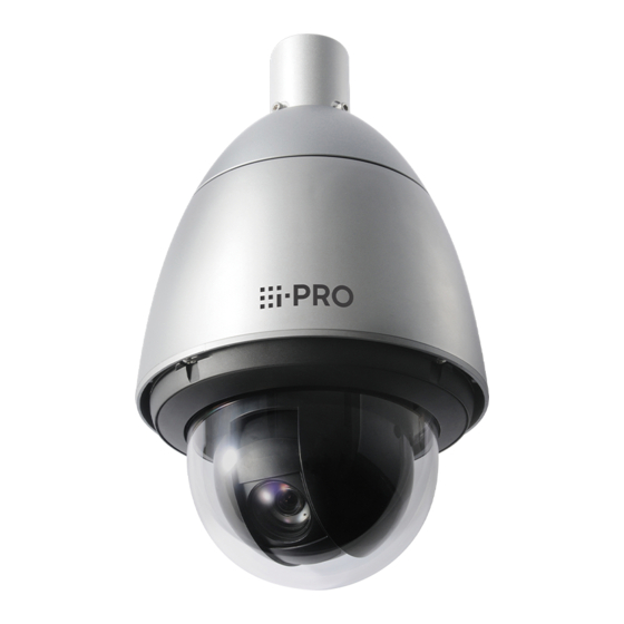
Network Camera
WV-X6531N / WV-X6531NRF
Model No.
WV-X6531NEG / WV-X6511N
WV-S6530N
WV-X6531N
• Before attempting to connect or operate this product, please read these instructions carefully and
save this manual for future use.
• Before reading this manual, be sure to read the Important Information(included in the CD-ROM).
• For information about how to perform the settings and how to operate the camera, refer to the
Operating Instructions on the provided CD-ROM.
• The model number is abbreviated in some descriptions in this manual.
• WV-X6531NRF and WV-X6531NEG are the same model as the Network Camera WV-X6531N.
For U.S. and Canada:
For Europe and other countries:
i-PRO Co., Ltd.
i-PRO Americas Inc.
Fukuoka, Japan
https://www.i-pro.com/
https://www.i-pro.com/
i-PRO EMEA B.V. UK Branch
1010 Cambourne Business Park,
Cambridgeshire CB23 6DP
Authorised Representative in EU:
i-PRO EMEA B.V.
Laarderhoogtweg 25, 1101 EB
Amsterdam, Netherlands
© i-PRO Co., Ltd. 2022
Ns0217-7042
PGQX2158SA
Printed in China
Important safety instructions
1) Read these instructions.
2) Keep these instructions.
3) Heed all warnings.
4) Follow all instructions.
5) Do not block any ventilation openings. Install in accordance with the manufacturer's instructions.
6) Do not install near any heat sources such as radiators, heat registers, stoves, or other apparatus (including
amplifiers) that produce heat.
7) Only use attachments/accessories specified by the manufacturer.
8) Use only with the cart, stand, tripod, bracket, or table specified by the manufacturer, or sold with the
apparatus. When a cart is used, use caution when moving the cart/apparatus combination to avoid injury
from tip-over.
S3125A
9) Unplug this apparatus during lightning storms or when unused for long periods of time.
10) Refer all servicing to qualified service personnel. Servicing is required when the apparatus has been dam-
aged in any way, such as power-supply cord or plug is damaged, liquid has been spilled or objects have
fallen into the apparatus, the apparatus has been exposed to rain or moisture, does not operate normally,
or has been dropped.
Troubleshooting
Before requesting service, refer to the Important Information (included in the CD-ROM) and "Troubleshooting"
in the Operating Instructions (included in the CD-ROM) and confirm the trouble.
Open Source Software
• This product contains open source software licensed under GPL (GNU General Public License), LGPL
(GNU Lesser General Public License), etc.
• Customers can duplicate, distribute and modify the source code of the software under license of GPL and/
or LGPL.
• Refer to the "readme.txt" file on the provided CD-ROM for further information about open source software
licenses and the source code.
• Please note that we shall not respond to any inquiries regarding the contents of the source code.
WARNING:
NOTE: This equipment has been tested and found
• To prevent injury, this apparatus must be secure-
to comply with the limits for a Class A digital
ly attached to the wall/ceiling in accordance with
device, pursuant to Part 15 of the FCC Rules.
the installation instructions.
These limits are designed to provide reasonable
• All work related to the installation of this product
protection against harmful interference when the
should be made by qualified service personnel
equipment is operated in a commercial environ-
or system installers.
ment. This equipment generates, uses, and can
• The installation shall be carried out in accor-
radiate radio frequency energy and, if not installed
dance with all applicable installation rules.
and used in accordance with the instruction man-
• The connections should comply with local elec-
ual, may cause harmful interference to radio com-
trical code.
munications.
• This equipment is compliant with Class A of
Operation of this equipment in a residential area is
CISPR 32. In a residential environment this
likely to cause harmful interference in which case
equipment may cause radio interference.
the user will be required to correct the interfer-
• Batteries (battery pack or batteries installed)
ence at his own expense.
shall not be exposed to excessive heat such as
sunlight, fire or the like.
FCC Caution: To assure continued compliance,
CAUTION:
(example - use only shielded interface cables
when connecting to computer or peripheral devic-
• Any changes or modifications not expressly
es). Any changes or modifications not expressly
approved by the party responsible for compli-
approved by the party responsible for compliance
ance could void the user's authority to operate
could void the user's authority to operate this
the equipment.
equipment.
• The network camera is only intended for a con-
nection to an ethernet or PoE+ network without
routing to the outside plant.
The model number and serial number of this
product may be found on the surface of the unit.
For Canada
You should note the model number and serial
CAN ICES-3(A)/NMB-3(A)
number of this unit in the space provided and
retain this book as a permanent record of your
purchase to aid identification in the event of
: Direct current symbol
theft.
: Alternating current symbol
Model No.
Serial No.
Disposal of Old Equipment and Batteries
Only for European Union and countries with recycling systems
These symbols on the products, packaging, and/or accompanying documents mean that used
electrical and electronic products and batteries must not be mixed with general household waste.
For proper treatment, recovery and recycling of old products and used batteries, please take them
to applicable collection points in accordance with your national legislation.
By disposing of them correctly, you will help to save valuable resources and prevent any potential
negative effects on human health and the environment.
For more information about collection and recycling, please contact your local municipality.
Penalties may be applicable for incorrect disposal of this waste, in accordance with national
legislation.
Note for the battery symbol (bottom symbol)
This symbol might be used in combination with a chemical symbol. In this case it complies with the
requirement set by the Directive for the chemical involved.
About notations
The following notations are used when describing the functions limited for specified models. The functions
without the notations are supported by all models.
X6531
X6531
:The functions with this notation are available when using the model WV-X6531N.
:The functions with this notation are available when using the model WV-X6511N.
X6511
S6530
:The functions with this notation are available when using the model WV-S6530N.
About the user manuals
Product documentation is composed of the following documents.
• Installation Guide (this document): Explains installation, mounting, cable connections, and network con-
nections. This manual uses the WV-X6531N as an example in the explanations.
• Important Information (included in the CD-ROM): Provides basic information about the product.
• Operating Instructions (included in the CD-ROM): Explains how to perform the settings and how to operate
this camera.
Adobe
®
Reader
®
is required to read these operating instructions on the provided CD-ROM.
When the Adobe Reader is not installed on the PC, download the latest Adobe Reader from the Adobe web site
and install it.
The external appearance and other parts shown in this manual may differ from the actual product within the
scope that will not interfere with normal use due to improvement of the product.
Standard accessories
Installation Guide
CD-ROM*
1
.......................................................... 1 pc.
(this document) ................................................... 1 pc.
Code label*
........................................................ 1 pc.
2
IMPORTANT SAFETY INSTRUCTIONS ............... 1 pc.
*1 The CD-ROM contains the operating instructions and different kinds of tool software programs.
*2 This label may be required for network management. Use caution not to lose this label.
The following parts are used during installation procedures.
Cable cover ........................................................ 1 pc.
8P alarm cable ................................................... 1 pc.
Attachment pipe ................................................. 1 pc.
24 V AC power supply connector kit ....................1 set
Front/rear sunshields ...........................................1 set
(Power supply connector housing: 1 pc., Contact: 3 pcs.)
Front/rear sunshields fixing screw
Hexagon screw (M5)
........................................ 5 pcs.
*3
........................................ 2 pcs. (of them, 1 for spare)
Waterproof tape .................................................. 1 pc.
Rain wash coating caution label ...........................1 pc.
RJ45 waterproof connector cover ...................... 1 pc.
RJ45 waterproof connector cap ......................... 1 pc.
*3 The screws are necessary when installing the camera on a separately sold mount bracket.
Waterproof tape
For U.S.A.
Other items that are needed (not included)
Prepare the required parts for each installation method before starting the installation. The following
are the requirements for the various installation methods.
Installation method
AWhen hanging the camera from ceiling
Use the ceiling mount bracket (WV-Q121B
).
*2
BWhen installing the camera on a wall
Use the wall mount bracket (WV-Q122A
*2
).
*1
The minimum pull-out strength is the value per screw.
*2
For details on procedure for attaching mount bracket
and camera, read the operating instructions of each
mount bracket.
IMPORTANT:
• Prepare four mounting screws (M10) to be mount-
ed on ceiling and wall separately.
• Select screws according to the material of the
location that the camera will be mounted to. In this
case, wood screws and nails should not be used.
• If the mounting location such as plaster board is
too weak to support the total weight, the area shall
be sufficiently reinforced.
Preparations before installation
【1】 Prepare the cables from camera side.
◆ When the only necessary connection to
camera is an Ethernet cable
Use only RJ45 network cable coming from camera.
Do not remove the cable case. Use it as it is.
◆When using 24 V AC, EXT I/O device, or
audio I/O device
Remove the cable case fixed by five screws on the
upper part of camera and pull out power cable,
audio I/O cable, and alarm I/O cable stored in it.
Note:
• Do not use the removed cable case and five
screws.
The installation tasks are explained using 4 steps.
Step1
Step2
⇨
Fix the mount bracket
Making connections
and hang the camera
Step1 Fix the mount bracket and hang the camera
The following explains an example of installation using mount
bracket (locally procured).
The right figure shows an example of the camera mounted on a ceiling with a
mount bracket (locally procured).
When waterproofing, use waterproof material to fill in gaps and holes
between the attachment pipe and the mount bracket.
【1】Fix the attachment pipe (accessory) to the mount bracket
(locally procured).
① Fix the attachment pipe to the mount bracket.
② Fill the gap between the mount bracket and attachment pipe with
waterproof material (locally procured) such as silicon clay.
③ Pass the cables from the ceiling through the mount bracket.
①
②
(of them, 1 for spare)
Waterproof
material
⇨
Mount bracket
(locally procured)
Attachment pipe
(accessory)
Preparations
Please read "Precautions for installation" of "Important Information" in the
provided CD-ROM closely before starting installation/connection of the camera.
【2】Insert an SD memory card (locally
procured) as occasion demands.
* SDXC/SDHC/SD memory card is described as
SD memory card.
Insert an SD memory card following the procedure
Mounting
Minimum pull-out
shown below. For the detailed procedure, refer to
screw
strength*
Important Information on the provided CD-ROM.
1
M10 screws/
① Remove the main sunshield rear cover.
1411 N {317 lbf}
4pcs.
② Loosen two locking screws of water-resistant
cap and pull the water-resistant cap and
M10 screws/
toward you.
823 N {185 lbf}
4pcs.
③ Insert an SD memory card into the SD
memory card slot.
A
B
④ Attach water-resistant cap and sunshield rear
WV-Q121B
WV-Q122A
cover to the original position in order.
Recommended tightening torque of the water-
resistant cap locking screws:
◆When using Q121B (option) or Q122A (option)
⇒Go to Step 1 【3】 .
◆When using the mount bracket (locally procured).
Prepare a mount bracket.
The following figure shows an example of the camera mounted on a ceiling with a bracket.
IMPORTANT:
• The mount bracket (locally procured) should have the configuration that enables
fixation of safety wire from camera.
Cable case
⇒Go to Step 1 【1】 .
Alarm input/
RJ45 (female)
output·
Network
Audio input/
R 1-1/2, 11crest, deep 30 MAX
cable
(taper pipe thread)
output cable
Power
cable
RP 1-1/2, 11 crest,
deep 30 MAX
(parallel pipe thread)
60 mm {2-3/8 inches}
Main sunshield
rear cover
Installation
• Remove the camera using the reverse order of the installation procedures.
Step3
Step4
⇨
⇨
Fixing the camera
Configure the network
settings
【2】 Fix the mount bracket (locally procured) on the installation surface.
Fix a mount bracket to the installation surface on the ceiling by using appropriate bolts,
nuts or the like (locally procured).
Attachment
IMPORTANT:
pipe
• After waterproofing the hole for fixing mount
(accessory)
bracket and the port for pulling out the cable
on the installation surface, fix the mount
bracket on the installation surface.
• Adjust the length of cable from camera
attachment port of attachment pipe to cable
end to 150~160mm {5-29/32 inches~6-5/16
inches}. (If the cable that is pulled out is too
long, storage after wiring becomes difficult.
Adjust the cable length carefully.)
• For the number of fixing screws and the
minimum pull-out strength (per 1 pc.), refer to
③
the operating instructions of mount bracket
(locally procured).
• Ensure the minimum pull-out strength (per
1 pc.) that has sufficient allowance for total
⇨
mass of mount bracket (locally procured),
attachment pipe, and camera etc.
⇒Go to Step 1 【5】 .
150~160mm
{5-29/32 inches~
6-5/16 inches}
SD memory
card (with
label side
facing down)
SD memory
card slot
Water-resistant cap
0.69 N·m {0.51 lbf·ft}
25 mm {31/32 inches}
85 mm {3-11/32 inches}
Download and start [IP Setting Software] <Control No.:
C0123> or [i-PRO Configuration Tool (iCT)] <Control No.:
C0133> on our technical information support site (https://
i-pro.com/global/en/surveillance/training_support/support/
technical_information), and connect to the network.
150~160mm
{5-29/32 inches~
6-5/16 inches}
Advertisement

Related Manuals for i-PRO WV-X6500 Series


Summary of Contents for i-PRO WV-X6500 Series
- Page 1 6) Do not install near any heat sources such as radiators, heat registers, stoves, or other apparatus (including Step1 Step2 Step3 Step4 C0123> or [i-PRO Configuration Tool (iCT)] <Control No.: About the user manuals ⇨ ⇨ ⇨ amplifiers) that produce heat.
- Page 2 Special screw (fixing Adjust the orientation of cable cover so that the ① Make the i-PRO logo mark on the camera ALARM IN1 / Black & white input / Auto time adjustment input (Black) (EXT I/O 1) screw) (3 pcs.) installation information and procedure, refer to line part of cable cover faces front of the bracket.