Table of Contents
Advertisement
Instructions to printer
DO NOT PRINT THIS PAGE
color
This document is intended to be printed in
as a
5.5 (width) x 6.5 inch (length) booklet with stapled binding.
Use high-quality, glossy 20lb (75 g/m²) paper.
Print double-sided. Fold sheet of 8.5" x 11" in two, trim
length, and staple spine.
The European version can use A4 in place of 8.5" x 11".
Advertisement
Table of Contents

Related Manuals for Emerson RSTi-EP CPE200 Series


Summary of Contents for Emerson RSTi-EP CPE200 Series
- Page 1 Instructions to printer DO NOT PRINT THIS PAGE color This document is intended to be printed in as a 5.5 (width) x 6.5 inch (length) booklet with stapled binding. Use high-quality, glossy 20lb (75 g/m²) paper. Print double-sided. Fold sheet of 8.5” x 11” in two, trim length, and staple spine.
- Page 2 RSTi-EP CPE200 Series Controllers Quick Start Guide GFK-3109B Dec 2022...
-
Page 3: Table Of Contents
Update Firmware Webpage Password ............29 Reset to Factory Defaults ................30 Removable Data Storage Device (RDSD) ............. 31 Periodic Maintenance ..................32 Additional Information ..............33 General Contact Information ............... 35 RSTi-EP CPE200 Series Controllers Quick Start Guide GFK-3109B... -
Page 4: Initial Checks
As the consignee, it is your responsibility to register a claim with the carrier for damage incurred during shipment. Emerson will fully cooperate with you, however, should such action be necessary. After unpacking the equipment, record all serial numbers. Serial numbers are required if you should need to contact Customer Care during the warranty period. -
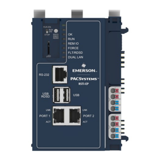
Page 5: Front Panel Description
Front Panel Description Figure 1: Front Panel View of EPXCPE205 RSTi-EP CPE200 Series Controllers Quick Start Guide GFK-3109B... - Page 6 Figure 2: Front Panel View of EPXCPE210/215/220/240 RSTi-EP CPE200 Series Controllers Quick Start Guide GFK-3109B...
-
Page 7: Displays And Led Indicators
Ethernet Ports. X = 1, 2, 3, or 4. LED that indicates Ethernet Link and Speed. Belongs Ethernet Port LED to the Ethernet Connector. LED that indicates Ethernet activity on the link. Ethernet Port LED Belongs to the Ethernet Connector. RSTi-EP CPE200 Series Controllers Quick Start Guide GFK-3109B... -
Page 8: Ethernet Port Leds
GREEN indicates 1 Gbps AMBER indicates 100 Mbps OFF indicates 10 Mbps (currently not supported per spec) Ethernet Activity (“ACT”): • GREEN indicates Link BLINKING GREEN indicates activity on the link Figure 2: 3-Position Switch RUN EN/RUN DIS/STOP RSTi-EP CPE200 Series Controllers Quick Start Guide GFK-3109B... -
Page 9: Front Display Leds
All PROFINET devices Green (steady) connected Unit is starting up (see LED REM IO Green (flashing) power-up sequence) Some PROFINET devices Amber (steady) connected The controller has a FORCE Amber (steady) forced value(s) RSTi-EP CPE200 Series Controllers Quick Start Guide GFK-3109B... - Page 10 Fault state Red (flashing) RDSD has failed Red (flashing) If RDSD is not being performed, indicates IP conflict detected DUAL LAN Green (steady) Dual LAN operating mode (EPXCPE205 Single LAN operating mode only) RSTi-EP CPE200 Series Controllers Quick Start Guide GFK-3109B...
-
Page 11: Run/Stop Switch
IP address than the programmer. The user must enter the new IP address in Target Properties PAC Machine Edition’s Inspector window before connecting and redownloading the program for it to be stored in the user flash. RSTi-EP CPE200 Series Controllers Quick Start Guide GFK-3109B... - Page 12 255.255.255.0 Gateway 0.0.0.0 *Dual LAN Mode is the default configuration for the EPXCPE205. EPXCPE210/215/220/240 Port 1 Port 2 Port 3 Port 4 Default IP 10.10.0.100 192.168.0.100 Address Subnet 255.255.255.0 Mask Gateway 0.0.0.0 RSTi-EP CPE200 Series Controllers Quick Start Guide GFK-3109B...
- Page 13 8.5 A + 1.5 A RSTI-EP internal 5V DC --> 1.5A@24V) Max. feed-in current for output 10 A modules Current consumption from system 116 mA current path I Connection data Type of connection Spring style RSTi-EP CPE200 Series Controllers Quick Start Guide GFK-3109B...
- Page 14 3 Blue: Ground 4 Blue: Ground 1- Green: Output current path supply voltage > 17 V 2- Red: Output current path supply voltage < 17 V DC 3 Blue: Ground 4 Blue: Ground RSTi-EP CPE200 Series Controllers Quick Start Guide GFK-3109B...
- Page 15 Figure 3: Power Feed Minimum Current Draw RSTi-EP CPE200 Series Controllers Quick Start Guide GFK-3109B...
- Page 16 Figure 4: Power Feed Maximum Current Draw RSTi-EP CPE200 Series Controllers Quick Start Guide GFK-3109B...
- Page 17 Figure 5: MicroSD Card Note: The MicroSD card needs to be inserted in the slot with the correct orientation. The pins of the card need to face towards the right side of the controller. RSTi-EP CPE200 Series Controllers Quick Start Guide GFK-3109B...
-
Page 18: Din Rail Installation
1. Begin by releasing the three closed levers located on the top of the CPE200 controller. Pull the levers toward the face of the controller to the open position. Figure 3: Release Levers RSTi-EP CPE200 Series Controllers Quick Start Guide GFK-3109B... - Page 19 2. Attach the controller to the DIN rail. The controller should rest on the rail, but be able to move freely side-to-side. Figure 4: Mount to DIN Rail RSTi-EP CPE200 Series Controllers Quick Start Guide GFK-3109B...
- Page 20 3. Slide the controller along the DIN rail into place. The controller should be in the left-most position and rest against a stop block (if applicable). Figure 5: Slide Controller to the Left RSTi-EP CPE200 Series Controllers Quick Start Guide GFK-3109B...
- Page 21 4. Repeat the steps for each of the IO modules. Connect the first IO module into connectors on the right side of the controller. Each subsequent IO module will connect to the previous module. Figure 6: Slide and Connect Each I/O Module RSTi-EP CPE200 Series Controllers Quick Start Guide GFK-3109B...
- Page 22 5. After all the I/O modules have been connected, mount the protective endplate into the last I/O module to protect the exposed connectors. Figure 7: Slide the End Plate into the Last Module RSTi-EP CPE200 Series Controllers Quick Start Guide GFK-3109B...
-
Page 23: Thermal Requirements
Thermal Requirements Figure 14: Minimum Distance Requirements RSTi-EP CPE200 Series Controllers Quick Start Guide GFK-3109B... -
Page 24: Controller Start-Up
A DIN rail, typically mounted in an enclosure • A computer running PAC Machine Edition (PME) configuration and programming software. PME Version 10.00.0.9413. Ethernet cable for connecting the programming computer running PME to the EPXCPE controller. RSTi-EP CPE200 Series Controllers Quick Start Guide GFK-3109B... -
Page 25: Basic Installation Steps
PAC Machine Edition) into Port 3. (For the EPXCPE205, connect the Ethernet cable to Ports 1 or 2.) Plug the Ethernet cable for the PROFINET network into Port 1 or Port 2. Apply power to the EPXCPE. RSTi-EP CPE200 Series Controllers Quick Start Guide GFK-3109B... -
Page 26: Led Behavior During Startup
2. The RUN LED will turn solid GREEN before turning it off. 3. The OK LED will turn solid GREEN and remain Figure 8: LED Illumination Sequence RSTi-EP CPE200 Series Controllers Quick Start Guide GFK-3109B... -
Page 27: Installation In Hazardous Areas
All protocols including MRP will be supported. Single LAN Mode Dual LAN LED will be OFF. LAN 2 (port 2) All protocols are supported except Dual LAN Mode PROFINET MRP. Dual LAN LED will turn solid GREEN. RSTi-EP CPE200 Series Controllers Quick Start Guide GFK-3109B... - Page 28 Figure 6: Single LAN Mode RSTi-EP CPE200 Series Controllers Quick Start Guide GFK-3109B...
- Page 29 Figure 7: Dual LAN Mode RSTi-EP CPE200 Series Controllers Quick Start Guide GFK-3109B...
- Page 30 EPXCPE210/215/220/240 Port 3. Unswitched. All protocols are supported except LAN 1 PROFINET. LAN 2 Ports 1 and 2. Switched. All protocols are supported. Figure 8: Network Configuration RSTi-EP CPE200 Series Controllers Quick Start Guide GFK-3109B...
- Page 31 4. To confirm the selection, press and hold the physical presence button on the controller until the webpage says to release it. 5. The controller will now reboot and come up in the new operating mode. RSTi-EP CPE200 Series Controllers Quick Start Guide GFK-3109B...
-
Page 32: Update Firmware Webpage Password
Login to the webpage and select Administrator and follow the process of changing the password. The webpage password can be updated while the PLC is in all modes (Run IO enabled, Run IO disabled, Stop, or Stop Fault). RSTi-EP CPE200 Series Controllers Quick Start Guide GFK-3109B... -
Page 33: Reset To Factory Defaults
Resets the IP addresses to their factory defaults shown in section Ethernet Ports b. Resets the Web page firmware password to its default setting. (Password is sierra) Deletes controller and IO faults d. Clears NVRAM RSTi-EP CPE200 Series Controllers Quick Start Guide GFK-3109B... -
Page 34: Removable Data Storage Device (Rdsd)
If one needs to restore the backup version, delete the PACS_folder on the USB device and then rename the folder PACS_folder_backup to PACS_folder at the root of the USB device. RSTi-EP CPE200 Series Controllers Quick Start Guide GFK-3109B... -
Page 35: Periodic Maintenance
To replace the RTC battery and reset the RTC time, refer to the RX3i, & RSTi-EP CPU Reference Manual (GFK-2222AS or later. Battery required: Lithium 3v BR2032 by Panasonic or Rayovac (Emerson Part Number: IC690ACC001B ) RSTi-EP CPE200 Series Controllers Quick Start Guide GFK-3109B... -
Page 36: Additional Information
GFK-2929 PACSystems RX3i PROFINET IO Controller User Manual GFK-2571 PROFINET I/O Devices Secure Deployment Guide GFK-2904 PACSystems DNP3 Outstation User Manual GFK-3103 PACSystems RSTi-EP User Manual GFK-2958 PACSystems Functional Safety Manual GFK-2956 RSTi-EP CPE200 Series Controllers Quick Start Guide GFK-3109B... - Page 37 (3) years, or ii) until the date on which we cease offering both spare parts and customer support for this particular version of this product, whichever occurs last. RSTi-EP CPE200 Series Controllers Quick Start Guide GFK-3109B...
-
Page 38: General Contact Information
All Rights Reserved. We reserve the right to modify or improve the designs or specifications of the products mentioned in this manual at any time without notice. Emerson does not assume responsibility for the selection, use, or maintenance of any product.
Need help?
Do you have a question about the RSTi-EP CPE200 Series and is the answer not in the manual?
Questions and answers