
Related Manuals for Emerson NELSON HEAT TRACE CM-2201


Summary of Contents for Emerson NELSON HEAT TRACE CM-2201
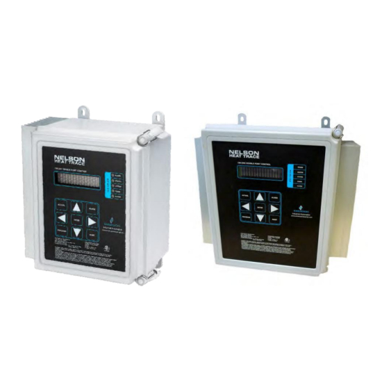
- Page 1 NELSON ™ CM-2201/CM-2202 HEAT TRACE CONTROLLERS Installation and Operating Instructions...
-
Page 2: Table Of Contents
Contents CM-2201/CM-2202 Introduction 1.1 Getting Started General Application Information Installation 3.1 Selecting Installation Location 3.2 Mounting 3.3 Wiring Initial Set-up 4.1 Display Modes 4.2 Password Protection 4.3 Security Levels General Operation 5.2 Display 5.3 Keypad LED Functions 5.5 Monitoring 5.6 Alarm Management 5.7 Current-Limiting Feature 5.8 Ground Faults 5.9 Soft Start Feature... - Page 3 CM-2201/CM-2202 Contents Appendix A – Specifications Appendix B – Wiring Diagrams Appendix C – Typical Installation Diagram Appendix D – Modbus Parameters Appendix E – RTD Tables Appendix F – Warranty ©2017 Nelson Heat Tracing Systems www.nelsonheaters.com GA2497 Rev.5...
-
Page 4: Introduction 4
Introduction CM-2201/CM-2202 1.1 Introduction The Nelson Heat Trace CM-2201 is designed to monitor and control one heating circuit in ordinary and Class I, Division 2, Class I, Zone 2, and Zone 2 hazardous locations. The CM-2202 can monitor/control two heating circuits in those same locations. -
Page 5: General Application Information 5
Application Information CM-2201/CM-2202 2.0 General Application Information The CM-2201/CM-2202 are designed to operate on input voltages between 100 and 277 Vac and 50/60Hz. Load switching is handled by a 2-Pole solid-state relay and can control resistive loads of 30A continuous @ 40°C ambient. The CM-2201/CM-2202 are designed to control heating circuits by monitoring one or two temperature inputs for each circuit via industry standard 3-wire, 100Ω, Platinum... -
Page 6: Installation 6
Installation and Initial Set up CM-2201/CM-2202 3.1 Installation implemented by connecting appropriate jumpers. Refer to Wiring Diagram in Appendix B for details. The CM-2201/CM-2202 must be installed only in areas for which it has been approved and in accordance with all applicable electrical codes and ordinances. -
Page 7: Initial Set-Up
CM-2201/CM-2202 Installation and Initial Set up 4.1 Initial Set-Up Upon initial power-up, the CM-2201/CM-2202 display will run self-check, display the software version and then start the main program. 4.2 Display Modes This feature determines what messages and functions are displayed during normal operations. If set to “normal user” only basic information is displayed. -
Page 8: General Operation 8
CM-2201/CM-2202 General Operation 5.1 General Operation 5.2.2 Navigation for CM2202 5.2 Display The CM2202 can monitor/control two separate heating The CM-2201/CM-2202 utilizes a 2 line x 16 character circuits (channels). The controller defaults to Channel 1 alphanumeric display viewable from the front keypad. upon first start-up. -
Page 9: Led Functions
General Operation CM-2201/CM-2202 5.3 Keypad 5.7 Current-Limiting Feature The keypad is “capacitive” touch sensitive and keys The Current-Limiting feature operates similarly to the are activated by simply touching the area of the Soft-Start in that it restricts the amount of time the desired key with a finger, even when wearing gloves. - Page 10 CM-2201/CM-2202 General Operation 5.9 Soft-Start Feature The Soft-Start feature enables self-regulating cables to be energized at low temperatures without causing excessive load on the electrical system and extending cable life by reducing cable internal heating due to inrush currents. The resistance of self-regulating cables decreases as the cables get colder, which results in higher current and can result in breaker trips if temperatures are very cold and the...
-
Page 11: On-Off Control
CM-2201/CM-2202 Control Modes 6.1 Control Modes If the Temperature setpoint is a specific value (eg 55C), then the setpoint will be maintained as The CM-2201/CM-2202 allows the user to select different per normal operation ONLY when the external control modes based on their individual process control signal is present or the external contact is closed parameters. -
Page 12: Setpoints
CM-2201/CM-2202 Programming 7.2.4 High Temp Alarm 7.1 Programming This value sets the High Temperature Alarm setpoint. It must be greater than the maintain temperature plus 7.2 Program-Setpoints deadband. To disable this alarm set the value to “Off”. When the measured temperature of either RTDA or RTDB (if 7.2.1 Setpoint Value activated) is greater than or equal to this set point, the High This message displays the name of the sub-menu when... -
Page 13: Heater Setup
Programming CM-2201/CM-2202 Low Voltage Alarm Continued 7.1.6 High Current Alarm Continued 1. Display Mode: All If Proportional Control or Current Limiting is enabled, all 2. Range: 85VAC to High Voltage Alarm, Off current measurements will be scaled to 100% power, based 3. - Page 14 CM-2201/CM-2202 Programming 7.2.3 Heater ID Control Type This selection allows for user defined Heater Identification. This selection determines the type of control method It provides a unique, identifiable tag or label for each heater used by the controller, either On-Off (Deadband) or circuit.
-
Page 15: System Setup
Programming CM-2201/CM-2202 RTD Operation Continued 7.2.8 Auto Test Cycle Functions requiring two RTDs to operate, such as Average, This value sets the frequency at which the Auto Test Cycle is Lowest, Highest and High Temperature Cutoff, will activated. Auto Test is a feature that exercises the system by operate in One RTD mode if one of the two RTDs fail. -
Page 16: Communications 18
CM-2201/CM-2202 Programming 7.3.3 Change Password 7.3.7 Default Display This selection allows the user to change the default password. This function specifies the information that will be The user is prompt to enter the old password, press [ENTER]. displayed when no key has been pressed for the Display If verified, the user is then to enter the new password, press Time out interval as described below. -
Page 17: Cm-2201/Cm
Programming CM-2201/CM-2202 Ground Fault Test 7.3.11 Reset Module This function will test the ground fault trip function of the This selection resets controller memory parameters to controller to ensure proper operation. When selected, the factory default values. If the controllers memory becomes controller will generate an artificial ground fault current;... - Page 18 CM-2201/CM-2202 Communications 8.0 Communications The Nelson Heat Trace CM-2201 supports a subset of the Modbus RTU protocol format that provides monitoring, ® programming, and control functions using Read (03) and Write (05-06) register commands. 8.1 General Information Serial Port: Select the serial portt hat corresponds to your RS-485 adapter.
- Page 19 Communications CM-2201/CM-2202 oldest alarm will be erased to allow for storage of the new alarm. To erase all alarms on alarm log, see below. To erase all alarms on the Alarm log from the remote terminal, send the following instruction: 04 05 0097 FF00 3D83 04 = controller Modbus number 05 = Modbus function code...
- Page 20 CM-2201/CM-2202 Troubleshooting 9.1 Troubleshooting When wiring to theCM2201/CM2202, the terminals are marked as follows: 9.2 Operator Checks Terminal No. Description Upon receipt of the controller, or to check the controller GND Bus Shield for an indication of normal operation, follow the RTD A Source (RED) operational procedures shown below.
- Page 21 Troubleshooting CM-2201/CM-2202 Note: Ensure you refer to the correct RTD table for the type 3. Unstable Temperature (Continued) of RTD you are using. d) Check one by one if the all RTD leads are connected to the 2. Temperature Verification ( Continued) connector.
- Page 22 CM-2201/CM-2202 Troubleshooting High Current Warning/Alarm (Continued) 9.4.1 High RTD A/ RTD B Temperature Reading Cause of Warning/Alarm: This warning/alarm appear when the temperature exceeds the • Warning/Alarm setting too close to normal operating current HIGH RTD WARNING/ALARM temperature setting. • High in-rush current from “cold start” of self regulating cable Cause of Warning/Alarm: •...
- Page 23 Troubleshooting CM-2201/CM-2202 Switch Failure 9.3.7 GFI Alarm (Continued) This alarm indicates that the controller senses current flow Cause of Alarm: when the output switch should • Trip setting too close to normal leakage current • Damaged cable insulation and/or moisture present be off.
- Page 24 CM-2201/CM-2202 Maintenance 10.0 Maintenance The CM-2201/CM-2202 should be regularly maintained as follows: a) Check fit of door gasket and adjust as required. Clean door gasket. b) Verify that moisture is not entering enclosure; repair as required. c) Check terminals to ensure connections are secure. d) Check wiring for any signs of overheating.
-
Page 25: Appendix A- Specifications
Appendices CM-2201/CM-2202 Appendix A– Specifications Model: CM-2201/CM-2202 110– 277Vac,30Amps(Solid State Rating: Relays) Maximum Current: 30 Amps per Channel Frequency: 50 or 60 Hz Solid State Relay (DPST) Switching: Normally Open (NO) Enclosure: NEMA 4X Alarm Outputs: 1. 24 VACto277 VAC@Max.0.5 Amps (Solid State Relay - requires Min. 100mA load) 2. -
Page 26: Appendix B - Wiring Diagrams
Appendices CM-2201/CM-2202 Appendix B - Wiring Diagram: CM-2201 Notes: 1. Solid State Contact 2. Install Jumper at JP1 (120 OHM Resistor) on both terminals if CM-2201 is last device on network. Else install jumper on one terminal only of JP1. 3. - Page 27 CM-2201/CM-2202 Appendices Appendix B - Wiring Diagram: CM-2202 Notes: All Alarms Output are SSR N.O. All RTD’s must have the Shield connected to Ground Bus. Remove Jumper JP1 only if the controller is in RS485 Network AND is not the last unit on the Network. Connect Power Supply Jumpers PJ1 &...
-
Page 28: Appendix C - Typical Installation Diagram
Appendices CM·2201/CM·2202 Appendix C - Typical Installation Diagram PAJ'IEL BOARD RS485/Al.ARM WIRING POWER CONNECTION CONDUIT DRAIN R'TIJA -HEA TRACE CABLE CM2202 POWER CONNECTION CKT1 POWE;R CONNECTION CON!ltJIT DRAIN R'TIJA HEAT TRACE CABL'E CT2 GA2497 Rev.5 ©2017 Nelson Heat Tracing Systems www.nelsonheaters.com DRAFT... -
Page 29: Appendix D - Modbus Parameters
Appendices CM-2201/CM-2202 Appendix D ©2017 Nelson Heat Tracing Systems www.nelsonheaters.com GA2497 Rev.5 DRAFT... - Page 30 Appendices CM-2201/CM-2202 ©2017 Nelson Heat Tracing Systems www.nelsonheaters.com GA2497 Rev.5 DRAFT...
- Page 31 Appendices CM-2201/CM-2202 ©2017 Nelson Heat Tracing Systems www.nelsonheaters.com GA2497 Rev.5 DRAFT...
- Page 32 CM-2201/CM-2202 Appendices ©2017 Nelson Heat Tracing Systems www.nelsonheaters.com GA2497 Rev.5 DRAFT...
- Page 33 CM-2201/CM-2202 Appendices ©2017 Nelson Heat Tracing Systems www.nelsonheaters.com GA2497 Rev.5 DRAFT...
- Page 34 CM-2201/CM-2202 Appendices ©2017 Nelson Heat Tracing Systems www.nelsonheaters.com GA2497 Rev.5 DRAFT...
- Page 35 Appendices CM-2201/CM-2202 ©2017 Nelson Heat Tracing Systems www.nelsonheaters.com GA2497 Rev.5 DRAFT...
- Page 36 Appendices CM-2201/CM-2202 ©2017 Nelson Heat Tracing Systems www.nelsonheaters.com GA2497 Rev.5 DRAFT...
- Page 37 Appendices CM-2201/CM-2202 ©2017 Nelson Heat Tracing Systems www.nelsonheaters.com GA2497 Rev.5 DRAFT...
- Page 38 CM-2201/CM-2202 Appendices ©2017 Nelson Heat Tracing Systems www.nelsonheaters.com GA2497 Rev.5 DRAFT...
-
Page 39: Appendix E - Rtd Tables
CM-2201/CM-2202 Appendices Appendix E - RTD Tables Temperature Conversion Platinum Resistance (-200°C to 239°C) Temperature Coefficient - 0.00385 Ohms/Ohm/OC °C Ohms °C Ohms Ohms °C Ohms °C Ohms °C Ohms -200 18.49 -137 45.11 70.73 95.69 119.78 143.80 -199 18.93 -136 45.52 71.13... - Page 40 Appendices CM-2201/CM-2202 Appendix E - RTD Tables Temperature Conversion Platinum Resistance (-200°C to 239°C) Temperature Coefficient - 0.00385 Ohms/Ohm/OC -163 34.27 85.06 109.73 133.94 157.31 -162 34.69 -100 60.25 85.46 110.12 134.32 157.69 -161 35.11 60.66 85.85 110.51 158.06 61.06 86.25 110.90 134.70...
- Page 41 CM-2201/CM-2202 Appendices Appendix E - RTD Tables Temperature Conversion Platinum Resistance (240°C to 629°C) Temperature Coefficient - 0.00385 Ohms/Ohm/OC 192.99 214.86 236.31 277.56 297.72 193.35 215.22 257.32 277.90 298.04 193.71 236.65 257.66 278.23 298.37 215.57 237.00 258.00 278.56 298.70 194.07 215.93 237.35 258.34...
- Page 42 Appendices CM-2201/CM-2202 Appendix E - RTD Tables Temperature Conversion Platinum Resistance (240°C to 629°C) Temperature Coefficient - 0.00385 Ohms/Ohm/OC 226.17 247.38 268.17 288.52 308.44 204.88 226.52 247.72 268.50 288.85 308.76 205.23 226.87 248.07 268.84 289.18 309.09 205.59 227.22 248.41 269.18 289.51 309.41 205.95...
- Page 43 CM-2201/CM-2202 Appendices Appendix E - RTD Tables 100W Platinum RTD Ω- 0.00385 coefficient °F °F Resistance in Ohms -320 20.44 20.20 19.96 19.72 19.48 19.24 19.00 18.76 18.52 -320 -310 22.83 22.59 22.35 22.11 21.87 21.63 21.39 21.16 20.92 20.68 20.44 -310 -300...
- Page 44 Appendices CM-2201/CM-2202 Appendix E - RTD Tables 100W Platinum RTD Ω- 0.00385 coefficient °F °F Resistance in Ohms 93.03 92.82 92.60 92.38 92.16 91.94 91.72 91.50 91.29 91.07 90.85 93.03 93.25 93.47 93.69 93.91 94.12 94.34 94.56 94.78 95.00 95.21 95.21 95.43 95.65 95.87...
- Page 45 CM-2201/CM-2202 Appendices Appendix E - RTD Tables 100W Platinum RTD Ω- 0.00385 coefficient °F °F Resistance in Ohms 163.12 163.33 163.53 163.74 163.95 164.15 164.36 164.57 164.77 164.98 165.18 165.18 165.39 165.60 165.80 166.01 166.21 166.42 166.63 166.83 167.04 167.24 167.24 167.45 167.66 167.86 168.07 168.27 168.48...
- Page 46 Appendices CM-2201/CM-2202 Appendix E - RTD Tables 100W Platinum RTD Ω- 0.00385 coefficient °F °F Resistance in Ohms 231.27 231.47 231.66 231.86 232.05 232.24 232.44 232.63 232.83 233.02 233.21 233.21 233.41 233.60 233.80 233.99 234.18 234.38 234.57 234.77 234.96 235.15 235.15 235.35 235.54 235.73 235.93 236.12...
- Page 47 CM-2201/CM-2202 Appendices Appendix E - RTD Tables 100W Platinum RTD Ω- 0.00385 coefficient °F °F Resistance in Ohms 1000 293.48 293.66 293.84 294.03 294.21 294.39 294.57 294.76 294.94 295.12 295.30 1000 1010 295.30 295.48 295.67 295.85 296.03 296.21 296.40 296.58 296.76 296.94 297.12...
-
Page 48: Appendix F - Warranty
Group’s quotation, and in the event that actual operating conditions or Appleton Grp LLC d/b/a Appleton Group. The Appleton, O-Z/Gedney, SolaHD, EasyHeat, Nelson and Emerson logos are registered in the U.S. Patent and Trademark Office. EasyHeat, Inc. is a wholly owned subsidiary of Appleton Grp LLC. All other product or service names are the property of their registered owners.
Need help?
Do you have a question about the NELSON HEAT TRACE CM-2201 and is the answer not in the manual?
Questions and answers