Table of Contents
Advertisement
Quick Links
Electrical &
Hardware
Installation Guide
Installing the Data Network
Do NOT connect DALI or mains power to DyNet data terminals.
A
1.
The data cable is connected to all devices as per the project
schematic following correct color code and DyNet terminations.
Devices may be wired in any order.
2.
The recommended connection method is to 'daisy chain' devices in sequence, starting at the first device,
then looping in and out of each device, with a single cable terminating at the last device. There should
not be any branching, and only the first and last device should terminate a single cable, all other devices
should terminate two cables.
3.
A data cable that is connected to an energized device is live. Do not cut or terminate live data cables.
4.
The cable tail can be returned to the original distribution board. Ground wire and power wire (+V) can be
connected in a loop but D+ and D– must NOT be connected in a loop. Do not connect power wire (+V) in
a loop where segmentation is required between network sections that have multiple power supplies
deployed, to ensure Network cable current limits are not exceeded.
5.
Maximum allowed power supply rating and data cable current for any section of the network is the
lowest of either 2 Amps or the Cable rating per local wiring code or cable manufacturer specification.
Where required, apply power wire (+V) segmentation per network design to prevent exceeding limits. Use
only approved DyNet power supplies to ensure network reliability and safety.
6.
The data cable should be segregated from mains cables by a minimum of 50 mm (2 in) for shielded cable
and 300 mm (12 in) for unshielded cable or as per local wiring code specification (whichever is greater).
If the data cable crosses over any mains cables, it should cross at 90°, whilst maintaining correct
segregation. The wiring segregation distance may be reduced if either data cables, mains cables or both
are fitted in separate grounded metal conduits.
7.
On Button Panels and Sensors, the Shield wires must be terminated into the shield terminal. Shield wires
are automatically earthed on each controller. For controllers that do not have a shield terminal, the shield
should be twisted together and taped to the cable sheath to maintain continuity.
8.
The maximum recommended length for DyNet cables between two
network bridges is 800 m (2620 ft). For cable runs over 300 m (1000 ft),
(or baud rates over 9600 bps), 120 Ohm, 2 W end-of-line resistors must
be installed across the D+ and D- terminals of the DyNet connector
strip on the first and last devices.
16
th
February 2022
www.philips.com/dynalite
Advertisement
Table of Contents

Subscribe to Our Youtube Channel
Related Manuals for Philips Dynalite


Summary of Contents for Philips Dynalite
- Page 1 800 m (2620 ft). For cable runs over 300 m (1000 ft), (or baud rates over 9600 bps), 120 Ohm, 2 W end-of-line resistors must be installed across the D+ and D- terminals of the DyNet connector strip on the first and last devices. February 2022 www.philips.com/dynalite...
- Page 2 Dynalite Hardware ........Installation Guide ........Page 2 ........Data Cable Termination Strip off outer jackets of cables being daisy chained. Shielded cables only: Cut foil or braid flush to outer jacket. DO NOT cut drain (shield) wire. Strip insulation from each of the conductors.
-
Page 3: Recommended Cable Types
(24 AWG) wires as a conservative limit, provided GND and +V use a twisted pair in parallel as shown on drawings. • Other STP CAT5/6 cable types may be used, provided their specifications meet or exceed Dynalite specifications and local Wiring Code requirements. •... - Page 4 Number of devices on a single cable run The Dynalite network uses a trunk and spur topology. Trunks can be RS-485 or Ethernet. Spurs are RS-485 only. Each spur is connected to a network gateway that connects to the trunk network. If required, a spur can be separated into network segments with network isolator devices (such as the DDNI485).
- Page 5 Dynalite Hardware ........Installation Guide ........Page 5 ........Standard terminations DyNet-STP-CABLE-LSZH Signal Color Shield Earth (cover with insulated sleeve) Green/Green-White Paralleled for Ground Blue Data + Blue-White Data – Orange/Orange-White Paralleled for +V 12/24 VDC Spare pair can potentially be used Brown/Brown-White to replace a damaged pair.
- Page 6 Dynalite Hardware ........Installation Guide ........Page 6 ........Other control cable types There are two types of data cable commonly used to connect to electronic lamp drivers (ballasts). 1-10V cabling 1-10V uses mains rated polarized cabling; typically, a single pair “figure-8” cable. Positive wire may have a dashed line.
- Page 7 Dynalite Hardware ........Installation Guide ........Page 7 ........DALI Cabling DALI and DSI use mains rated non-polarized cabling; typically, a single pair “figure-8” cable or more often combined with lighting gear supply cabling, DALI has free wiring topology (daisy-chain, star or combined) but ring shaped connections should be avoided.
- Page 8 Dynalite Hardware ........Installation Guide ........Page 8 ........DALI Topology DALI Broadcast Each independent lighting group requires individual wiring. Open Offi ce Meeting room Offi ce 1 DALI Addressable The same DALI bus wiring to DALI enumerated lamp drivers. A single universe has up to 64 driver addresses.
- Page 9 (Recommend approximately 50 drivers per universe to allow for expansion). From 2022, the DDBC320-DALI joins the DDBC120-DALI in supporting a limited number of Dynalite user interface/sensor devices on each universe. For more information, refer to the DALI Multimaster device and driver table (on previous page), and specification sheets.
- Page 10 Dynalite Hardware ........Installation Guide ........Page 10 ........Example Installations DIN rail mounted controllers Wall mounted controllers February 2022 www.lighting.philips.com/dynalite...
- Page 11 Dynalite Hardware ........Installation Guide ........Page 11 ........Installing Gateways In multi-story buildings, each floor typically contains an independent network segment called a spur. Spurs can be joined via network gateways to a trunk network (RS-485 or Ethernet) installed in a riser linking all floors together.
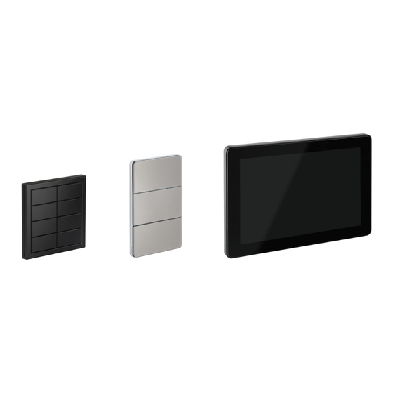
- Page 12 Dynalite Hardware ........Installation Guide ........Page 12 ........Installing user interfaces Follow device Installation Instructions to select appropriate physical placement of user interfaces. Take care not to damage the wall surface surrounding user interfaces particularly when they have the light wash feature (PDTS, PAxBP, PADP and PATP).
-
Page 13: Installing Sensors
Motion detection positioning Typical detection range is measured at ≤25°C (77°F). A single Dynalite sensor can perform motion detection, light regulation and IR receive simultaneously. Range is reduced at ambient temperatures above 32°C (90° F) Sensors must receive specified supply voltage 15 V or 24 V ± 10% from the DyNet network. If necessary, add a network power supply to ensure adequate network voltages are maintained during day to day fluctuations. - Page 14 Dynalite Hardware ........Installation Guide ........Page 14 ........Light regulation positioning When positioning sensors, there are two methods of light regulation to consider: (speak to design engineer if unsure): • If the sensor is used for Closed loop sensing, then position the sensor so it sees a mixture of indoor and outdoor light.
- Page 15 Dynalite Hardware ........Installation Guide ........Page 15 ........Installing dry contact input devices DLLI8I8O and DPMI940-DALI Safety Note: DALI Dry Contact inputs are FELV (not touch safe) and they are galvanically connected to the DALI network. ONLY Dry Contact switches with mains rated safety isolation shall be interfaced.
-
Page 16: Power-Up Tests
For touchscreens, use the Preset buttons or Sliders on the page to dim channels and confirm that the touchscreen is communicating with the network. All devices are pre-programmed for out-of-the-box operation. Dynalite load controllers (dimmers) are set to provide full output by default, irrespective of having the network connected. - Page 17 Dynalite Hardware ........Installation Guide ........Page 17 ........Controller Service Switch functions The relevant Service Switch functions are: • 3 pushes = All Channels 100%. You should do this to normalize the connected driver settings. (DALI Broadcast Channels will setup the connected drivers with Min/Max/PowerOn/SystemFail levels, and 2 second Fade Time).
-
Page 18: Fault Finding
Dynalite Hardware ........Installation Guide ........Page 18 ........Fault finding DyNet bus issues After completing the power up tests, all controllers should react to a single button push message. If not, check for any discrepancies between the installation and the installation instructions and check troubleshooting symptoms. - Page 19 Dynalite Hardware ........Installation Guide ........Page 19 ........DALI Bus Issues Tools required: • Digital Oscilloscope 10 MHz bandwidth or greater • Safety Isolated Differential Probes 1 MHz bandwidth or greater Measurements are taken between DALI wires. This method is the most comprehensive and can uncover issues which other "static"...
-
Page 20: Troubleshooting Tables
Dynalite Hardware ........Installation Guide ........Page 20 ........Troubleshooting tables Load Controller Issues Probable cause Solution Symptom • Faulty mains supply Check power supply connections to the Controller does not operate at connection. device. Check Fuse if fitted. all. No Service LED activity. - Page 21 Dynalite Hardware ........Installation Guide ........Page 21 ........Button Panel, Sensor and Dry Contact issues Probable cause Solution Symptom Check power supply to the device. • Wiring issue on DyNet bus. Check for broken wires. Device does not operate or •...
- Page 22 (incompatibility) DTK622-232). • Third party system (such as Install a suitable conversion such as AMX, DMX or gateway/interface (for example, a Dynalite controls operate Crestron) is streaming DTK622-232). intermittently messages and overriding DyNet. Disable or isolate DMX. To ensure safety and prevent damage to the system, appropriate isolation shall be provided. Only SELV/Class 2 (UL) systems shall be connected to non-isolated DyNet interfaces.
- Page 23 Philips and the Philips Shield Emblem are registered trademarks of Koninklijke Philips N.V. All other trademarks are owned by Signify Holding or their respective owners.
Need help?
Do you have a question about the Dynalite and is the answer not in the manual?
Questions and answers