Table of Contents
Advertisement
Quick Links
Advertisement
Chapters
Table of Contents

Related Manuals for GW Instek GDM-531


Summary of Contents for GW Instek GDM-531
- Page 1 Handheld Digital Multimeter GDM-531 USER MANUAL ISO-9001 CERTIFIED MANUFACTURER...
- Page 2 This manual contains proprietary information, which is protected by copyright. All rights are reserved. No part of this manual may be photocopied, reproduced or translated to another language without prior written consent of Good Will company. The information in this manual was correct at the time of printing. However, Good Will continues to improve products and reserves the rights to change specification, equipment, and maintenance procedures at any time without notice.
-
Page 3: Table Of Contents
Table of Contents Table of Contents SAFETY INSTRUCTIONS ..........4 GETTING STARTED ............7 GDM-531 Overview ..........8 OPERATION ..............10 Operating Instructions .......... 11 AC/DC Voltage Measurement ........ 11 Resistance Measurement ........13 Continuity Measurement ........15 Diode Measurement ..........16 Capacitance Measurement ........ -
Page 4: Safety Instructions
GDM-531 User Manual AFETY INSTRUCTIONS This chapter contains important safety instructions that you must follow during operation and storage. Read the following before any operation to ensure your safety and to keep the instrument in the best possible condition. Safety Standards EN 61326-1;... - Page 5 SAFETY INSTRUCTIONS Electrical Symbols These safety symbols may appear in this manual or on the instrument. Low battery Direct current Alternating current Warning Double insulation Caution, possibility of electric shock Grounding Comply with European Union Standards It is applicable to test and measuring circuits CAT III connected to the distribution part of the building's low-voltage MAINS installation.
- Page 6 GDM-531 User Manual Safety Instructions Do not use the device if the rear cover is not covered up or it will pose a shock hazard Do not use the device if the device or test leads appear damaged ...
-
Page 7: Getting Started
GETTING STARTED ETTING STARTED This chapter describes the GDM-531 in a nutshell, including its main features and front/ rear panel introduction. GDM-531 Overview ..........8 Overview ..................... 8 Features ....................8 Accessories ..................8 External Structure ................9 Function Buttons ................9... -
Page 8: Gdm-531 Overview
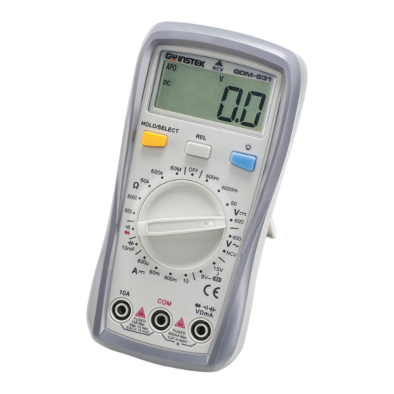
GDM-531 User Manual GDM-531 Overview Overview GDM-531 is a 6000 count palm sized multimeter with auto and manual range respectively. These CE certified multimeters are CAT III 600V, which can withstand 6000kV surge voltage. GDM-531 is designed with high voltage warning and over range alarm, making this series great for a wide range of measurement needs. - Page 9 GETTING STARTED External Structure Item Index Description LCD display Functional buttons Functional dial 10A input terminal COM input terminal Other input terminals Function Buttons Button Description HOLD/SELECT: Press to turn on/off data hold function (except at continuity/diode position) The capacitance mode, press this button to remove the base.
- Page 10 GDM-531 User Manual PERATION Operating Instructions .......... 11 AC/DC Voltage Measurement ........ 11 Resistance Measurement ........13 Continuity Measurement ........15 Diode Measurement ..........16 Capacitance Measurement ........17 DC Current Measurement ........19 Battery Measurement ..........21 1.5V battery: resistance=30Ω ............22 9V battery: resistance=900Ω...
-
Page 11: Operation
OPERATION Operating Instructions To avoid false reading, replace the battery if the battery low power symbol appears. Also pay special attention to the warning sign besides the test lead housing, indicating that the tested voltage or current must not exceed the values listed on the device. AC/DC Voltage Measurement Wire Connection Diagram... - Page 12 GDM-531 User Manual Do not input voltage over 600Vrms, or it may pose shock hazard. Warnings Be cautious when measuring high voltage Before using the device, if the voltage is unknown, switch the dial to the maximum...
-
Page 13: Resistance Measurement
OPERATION Resistance Measurement Wire Connection Diagram 1. Switch the dial to resistance position. Steps of Measurement 2. Insert the red test lead to VΩmA jack, black to COM jack. 3. Connect test leads with the load in parallel. 4. Reading is displayed. - Page 14 GDM-531 User Manual If the resistor is open or over the range, the “OL” symbol will be displayed on the screen. Note Before measuring resistance, switch off the power supply of the circuit, and fully discharge all capacitors.
-
Page 15: Continuity Measurement
OPERATION Continuity Measurement Wire Connection Diagram 1. Switch the dial to continuity position. Steps of Measurement 2. Insert the red test lead to VΩmA jack, black to COM jack. 3. Connect test leads with the load in parallel. 4. Reading is displayed. Measured resistance >51Ω, circuit is in open status. -
Page 16: Diode Measurement
GDM-531 User Manual Diode Measurement Wire Connection Diagram 1. Switch the dial to diode position. Steps of Measurement 2. Insert the red test lead to VΩmA jack, black to COM jack. 3. Red test lead to positive pole, black to negative pole. -
Page 17: Capacitance Measurement
OPERATION Capacitance Measurement Wire Connection Diagram 1. Switch the dial to capacitance measurement. Steps of Measurement 2. Insert the red test lead to VΩmA jack, black to COM jack. 3. Reading is displayed. - Page 18 GDM-531 User Manual Switch off the power supply to the circuit, and fully discharge all capacitors Note Before measuring capacitors (especially for high voltage capacitors), please fully discharge them. If the tested capacitor is shorted or its capacity is over the specified range "OL"...
-
Page 19: Dc Current Measurement
OPERATION DC Current Measurement Wire Connection Diagram 1. Switch the dial to DC current position. Steps of Measurement 2. According to the current being measured. Insert the red test lead to VΩmA jack or 10A jack, black to COM jack. 3. - Page 20 GDM-531 User Manual Before measuring, switch off the power supply of the circuit. Note If the range of the measured current is unknown, select the maximum range and then accordingly reduce. There are fuses inside VΩmA jack and 10A jack.
-
Page 21: Battery Measurement
OPERATION Battery Measurement Wire Connection Diagram 1. Switch the dial to battery position. Steps of Measurement 2. Insert the red test lead to VΩmA jack or 10A jack, black to COM jack. 3. Connect red test lead to + pole of the battery, black to –... - Page 22 GDM-531 User Manual 1.5V battery: resistance=30Ω Indication Voltage ≥1.31 Good 0.95V~1.3V ≤0.94V 9V battery: resistance=900Ω Indication Voltage ≥7.8 Good 5.7V~7.7V ≤5.6V When the display shows Bad, you need to replace the battery Note If the battery voltage <0.2V, there is no...
-
Page 23: Ncv Measurement
OPERATION NCV Measurement Wire Connection Diagram 1. Switch the dial to NCV position. Steps of Measurement 2. Place the device near the measured object. "- "symbol indicates the intensity of the electric field. More "-"and the higher the buzzer frequency, the higher the electric field intensity. - Page 24 GDM-531 User Manual 3. Intensity of electric field. * "EF": 0 ~ 50mV * "-": 50 ~ 100mV * "--": 100 ~ 150mV * "---": 150 ~ 200mV * "----":>200mV...
-
Page 25: Others
OPERATION Others The device enters measurement status in 2 Additional Notes seconds after startup. Restart the device if”ErrE” appears. The device automatically shuts down if there is no operation for 15 minutes. You can wake up the device by pressing any key. To disable auto shutdown: switch the dial to OFF position and long press SELETE button until the device turn on. -
Page 26: Specifications
GDM-531 User Manual PECIFICATIONS General Specifications Max voltage between input terminal and earth grounding: 600Vrms Fuse Type: 10A Jack: F 10A H 600V Fuse Φ6x25mm (or Φ6×32mm) mA/μA Jack: F 600mA H 600V Fuse Φ6x32mm Display count: 6000 Overload indication: OL, refresh 3 times/s... -
Page 27: Technical Specifications
SPECIFICATIONS Technical Specifications Accuracy: ± (% of reading + numerical value in least significant digit slot), 1 year warranty Ambient temperature: 23˚C ± 5˚C (73.4˚F ± 9˚F) Ambient humidity: ≤75% RH To ensure accuracy, operating temperature should be within 18˚C ~ 28˚C. Note ... -
Page 28: Dc Voltage
GDM-531 User Manual DC Voltage Range Resolution Accuracy Position 600.0mV 0.1mV ±(0.7%+3) 6.000V/6000mV 0.001V/1mV ±(0.7%+3) 60.00V 0.01V ±(0.7%+3) 600.0V 0.1V ±(0.7%+3) Input impedance: About 10MΩ. Results might be unstable at mV range when no load is connected. The value becomes stable once the load is connected. -
Page 29: Resistance Measurement
SPECIFICATIONS Resistance Measurement Range Resolution Accuracy Position 600.0Ω 0.1Ω ±(1.0%+2) 6.000kΩ/6000Ω 0.1kΩ/1Ω ±(0.8%+2) 60.00kΩ 0.01kΩ ±(0.8%+2) 600.0kΩ 0.1kΩ ±(0.8%+2) 60.00MΩ 0.01MΩ ±(2.0%+5) Measurement result = reading of resistor – reading of shorted test leads Overload protection: 600Vrms Continuity, Diode Position Resolution Remark Set Value... -
Page 30: Capacitance
GDM-531 User Manual Capacitance Range Resolution Accuracy REL mode:±(4%+10) 9.999nF 0.001nF 99.99nF 0.01nF ±(4%+5) 999.9nF 0.1nF ±(4%+5) 9.999μF 0.001μF ±(4%+5) 99.99μF 0.01μF ±(4%+5) 999.9μF 0.1μF ±(4%+5) 9.999mF 0.001mF ±10% Overload protection: 600V-PTC Test capacitance≤200nF, adapt REL mode. DC Current... -
Page 31: Maintenance
MAINTENANCE AINTENANCE To avoid electric shock, make sure the probes are disconnected from the measured circuit before removing the rear cover. Make sure the WARNING rear cover is tightly screwed before using the instrument. General Maintenance Clean the case with a damp cloth and detergent. Do not use ... - Page 32 GDM-531 User Manual Fuse Replacement 1. Switch the dial to “OFF “position and remove Steps of the test leads from the input terminal. Replacement 2. Loosen the both screws on the rear cover, and then remove the rear cover to replace the fuse.
Need help?
Do you have a question about the GDM-531 and is the answer not in the manual?
Questions and answers