
Related Manuals for GW Instek GDM-397


Summary of Contents for GW Instek GDM-397
- Page 1 Handheld Digital Multimeter GDM-397, GDM-461 USER MANUAL GW INSTEK PART NO. 82DM-46100M01 ISO-9001 CERTIFIED MANUFACTURER...
- Page 2 This manual contains proprietary information, which is protected by copyright. All rights are reserved. No part of this manual may be photocopied, reproduced or translated to another language without prior written consent. The information in this manual was correct at the time of printing. However, we continue to improve our products and therefore reserve the right to change the specifications, equipment, and maintenance procedures at any time without notice.
-
Page 3: Table Of Contents
D. Testing for Continuity......................... 23 E. Testing Diodes ..........................25 F. Capacitance Measurement ......................28 G. Frequency Measurement ......................31 H. Temperature Measurement (GDM-397 only) ................33 Hold Mode ............................35 RANGE button ..........................36 MAX MIN button (GDM-397 only)....................36... - Page 4 GDM-397/GDM-461 User Manual Outputting Data ..........................37 The Use of Relative Value Mode ..................... 38 The BLUE button ..........................39 Turning on the Display Backlight (GDM-397 only) ................ 39 Sleep Mode (GDM-397 only) ......................39 GENERAL SPECIFICATIONS ....................40 Accuracy Specifications........................42 DC Voltage ............................
- Page 5 RS232C or USB serial port (optional), data hold, relative mode, peak measurement (GDM-461), low battery display, display backlight (GDM-397) and sleep mode. Except where noted, the descriptions and instructions in this User Manual apply to both GDM-397 and GDM-461.
-
Page 6: Overview
Item Description User Manual 1 piece Test Lead 1 pair K-type Temperature Probe (thermocouple) (GDM-397 only) 1 piece Multi-Purpose Socket 1 piece 9V Battery (NEDA1604, 6F22 or 006P)(built-in) 1 piece... -
Page 7: Safety Information
GDM-397/GDM-461 User Manual Safety Information This Meter complies with the IEC61010 standards: in pollution degree 2, overvoltage category (CAT. III 1000V, CAT. IV 600V) and double insulation. CAT III: Distribution level, fixed installation, with smaller transient overvoltages than CAT. IV. -
Page 8: Rules For Safe Operation
OVERVIEW Rules For Safe Operation Warning To avoid possible electric shock or personal injury, and to avoid possible damage to the Meter or to the equipment under test, adhere to the following rules: Before using the Meter inspect the case. Do not use the Meter if it is damaged or ... - Page 9 GDM-397/GDM-461 User Manual Use the proper terminals, function, and range for your measurements. Do not use or store the Meter in an environment with high temperature, humidity, explosives, inflammable materials or strong magnetic fields. The performance of the Meter may deteriorate when dampened.
-
Page 10: International Electrical Symbols
OVERVIEW A soft cloth and mild detergent should be used to clean the surface of the Meter when servicing. No abrasives and solvents should be used to prevent the surface of the Meter from corrosion or damage. The Meter is suitable for indoor use. ... -
Page 11: The Meter Structure
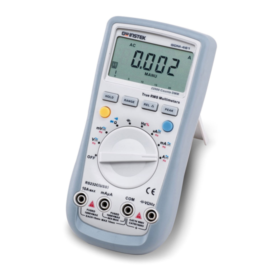
GDM-397/GDM-461 User Manual The Meter Structure (see figure 1) LCD display Functional buttons Yellow button Blue button Rotary switch Input terminals: figure 1... -
Page 12: Rotary Switch
Resistance Measurement Diode Test Continuity Test Capacitance Test Hz % Frequency and Duty Cycle Test ˚C Temperature in Celsius (GDM-397 only) ˚F Temperature in Fahrenheit (GDM-397 only) A DCA and ACA Measurement DCmA and ACmA Measurement 10A DC and AC Measurement... -
Page 13: Functional Buttons
Press to enter REL mode. Press again to exit REL mode For Model GDM-397: Press and hold for over 2 seconds to enter or exit RS232C or USB mode (optional). PEAK Press to step the display through Pmax and Pmin readings. -
Page 14: Display Symbols
OVERVIEW Display Symbols Symbol Meaning Data hold is active. Sleep Mode indicator Indicates negative reading. Indicator for AC measurement Indicator for DC measurement The Meter is in the auto range mode in which the Meter automatically selects the range with the best resolution. MANU Indicator for manual ranging mode. - Page 15 GDM-397/GDM-461 User Manual Ω, kΩ, MΩ Ω : Ohm. The unit of resistance. kΩ: Kilohm. 1 x 10 or 1000 ohms. MΩ: Megaohm. 1 x 10 or 1,000,000 ohms. V, mV V: Volts. The unit of voltage. mV: Millivolt. 1 x 10 or 0.001 volts.
-
Page 16: Measurement Operation
MEASUREMENT OPERATION EASUREMENT OPERATION A. DC/AC Voltage Measurement (see figure 2) GDM-397 GDM-461 figure 2... - Page 17 Connect the test leads across to the DUT. The measured value is shown on the display. GDM-397: Displays the effective value of a sine wave (mean value response). GDM-461: Displays the true rms value. Press Hz% (GDM-397) or the yellow button (GDM-461) to obtain the frequency and duty cycle value.
- Page 18 3000MΩ. This loading effect can cause measurement errors in high impedance circuits. If the circuit impedance is less than or equal to 10kΩ, the error is negligible (0.1% or less). For GDM-397: When measuring mV, you must press RANGE manually to enter mV range.
-
Page 19: Dc/Ac Current Measurement
GDM-397/GDM-461 User Manual B. DC/AC Current Measurement (see figure 3) GDM-397 GDM-461 figure 3... - Page 20 DC and AC current measurement function, press the BLUE button. Connect the test lead in series to the return line of the circuit to be tested. The measured value is shown on the display. GDM-397: Displays the effective value of sine wave (mean value response).
- Page 21 GDM-397/GDM-461 User Manual GDM-461: Displays the true rms value. Press Hz% (GDM-397) or the yellow button (GDM-461) to obtain the frequency and duty cycle value. Input Amplitude: (DC offset is zero) Input Amplitude:≥range×30% Frequency respouse:GDM-397: ≤400Hz, GDM-461: ≤ 1kHz...
-
Page 22: Resistance Measurement
MEASUREMENT OPERATION C. Resistance Measurement (see figure 4) mAuA VΩHz figure 4... - Page 23 GDM-397/GDM-461 User Manual Warning To avoid damaging the Meter or the DUT, disconnect power from the circuit and discharge all high-voltage capacitors before measuring resistance. To avoid harm to yourself, do not input voltages greater than DC 60V or AC 30V.
- Page 24 MEASUREMENT OPERATION Note The test leads can add 0.2Ω to 0.5Ω of error to the resistance measurement. To obtain precise readings for low-resistance measurements, short the leads beforehand to obtain the resistance of the test leads and use the relative measurement function button, REL , to automatically subtract the resistance of the test leads from the measured value.
-
Page 25: Testing For Continuity
GDM-397/GDM-461 User Manual D. Testing for Continuity (see figure 5) figure 5... - Page 26 The buzzer sounds continuously if the resistor to be tested is <10Ω. The buzzer does not sound if the resistor to be tested is >35Ω. Note GDM-397: open circuit voltage is around 0.45V GDM-461: open circuit voltage is around –1.2V When continuity testing has been completed, disconnect the connection between ...
-
Page 27: Testing Diodes
GDM-397/GDM-461 User Manual E. Testing Diodes (see figure 6) figure 6... - Page 28 MEASUREMENT OPERATION Warning To avoid possible damage to the Meter and to the device under test, disconnect the circuit power and discharge all high-voltage capacitors before testing diodes. To avoid harm to yourself, do not input voltages greater than DC 60V or AC 30V. Insert the red test lead into the Ω...
- Page 29 GDM-397/GDM-461 User Manual Connect the test leads to the proper terminals as said above to avoid errors. The LCD will display OL to indicate that the diode being tested is open or that the polarity is reversed. The Meter will display the forward voltage drop in voltage (V) units.
-
Page 30: Capacitance Measurement
MEASUREMENT OPERATION F. Capacitance Measurement (see figure 7) mAuA VΩHz figure 7... - Page 31 COM terminal. Set the rotary switch to . On the GDM-397, press BLUE button to select the nF measurement mode. At that time, the Meter will display a fixed value as shown below which is ...
- Page 32 MEASUREMENT OPERATION Connect the test leads to the DUT. The measured value shows on the display. Note It takes a longer time to measure a capacitance of more than 100μF. The LCD displays OL to indicate that the tested capacitor is shorted or it exceeds ...
-
Page 33: Frequency Measurement
GDM-397/GDM-461 User Manual G. Frequency Measurement (see figure 8) GDM-397 GDM-461 figure 8 Warning To avoid personal harm, do not attempt to input more than 30V rms when testing frequency. To measure frequency, connect the Meter as follows: Insert the red test lead into the Hz terminal and the black test lead into the... - Page 34 Hz measurement mode. Connect the test leads to the DUT. The measured value shows on the display. If you need to measure the duty cycle, press the Hz % button (GDM-397) or the yellow button (GDM-461) to select % measurement mode Note Input Amplitude: (DC offset is zero) ...
-
Page 35: Temperature Measurement (Gdm-397 Only)
GDM-397/GDM-461 User Manual H. Temperature Measurement (GDM-397 only) (see figure 9) figure 9... - Page 36 MEASUREMENT OPERATION Warning To avoid harm to yourself, do not input higher than DC 60V or AC 30V voltages. To measure temperature, connect the Meter as follows: Set the rotary switch to ˚C or ˚F Insert the temperature probe into the input terminal as shown on the figure 9. Place the temperature probe to the object being measured.
-
Page 37: Hold Mode
GDM-397/GDM-461 User Manual Hold Mode Warning To avoid possibility of electric shock, do not use Hold mode to determine if circuits are without power. The Hold mode will not capture unstable or noisy readings. The Hold mode is applicable to all measurement functions. -
Page 38: Range Button
Press and hold RANGE for over 2 seconds to return to auto ranging mode; the Meter beeps. MAX MIN button (GDM-397 only) Press MAX MIN to start recording of maximum and minimum values. Steps the display through high (MAX) and low (MIN) readings. The Meter enters manual ranging mode after pressing MAX MIN button. -
Page 39: Outputting Data
USB mode. The sleep mode feature will be disabled after entering RS232C or USB mode, the icon on the LCD will disappear (GDM-397 only). If the Meter is carrying out HOLD, MAX/MIN or REL measurement, the LCD will display the corresponding readings (Hold, Max, Min, REL) but the interface output will output the actual measurement present on the input terminals. -
Page 40: The Use Of Relative Value Mode
MEASUREMENT OPERATION The Use of Relative Value Mode The REL mode applies to all measurement functions except frequency/duty cycle measurement. It subtracts a stored value from the present measurement value and displays the result. For instance, if the stored value is 20.0V and the present measurement value is 22.0V, the reading would be 2.0V. -
Page 41: The Blue Button
It is used for selecting the required measurement function when there is more than one function at one position of the rotary switch. Turning on the Display Backlight (GDM-397 only) Warning In order to avoid mistakes arising from misread readings in insufficient light, please use the backlight function. -
Page 42: General Specifications
Fused Protection for 10A Input Terminal: 10A H 240V φ6x25mm. Display GDM-397: Maximum reading: 4000 (frequency 9999), analogue bar graph: 41 segments GDM-461: Maximum reading: 22000, analogue bar graph: 46 segments Measurement Speed: Updates 2~3 times/second. - Page 43 GDM-397/GDM-461 User Manual Temperature: Operating: 0˚C to +40˚C (32˚F to +104˚F). Storage: -10˚C to +50˚C (14˚F to +122˚F). Relative Humidity: ≤75% @ 0˚C ~ 30˚C below ≤50% @ 30˚C - 40˚C. Battery Type: 9V (NEDA1604 or 6F22 or 006P).
-
Page 44: Accuracy Specifications
GENERAL SPECIFICATIONS Accuracy Specifications Accuracy: ±(a% reading + b digits), guaranteed for 1 year. Operating temperature:18˚C ~28˚C. Relative humidity: <75%. DC Voltage GDM-397 Range Resolution Accuracy Input Impedance Fixed Value Input 40mV 0.01mV ±(0.8%+3) Around >3000MΩ 400mV 0.1mV ±(0.8%+3) 0.001V 1000V dc / 750V ac 0.01V... - Page 45 GDM-397/GDM-461 User Manual GDM-461 Range Resolution Accuracy Input Impedance Fixed Value Input 220mV 0.01mV ±(0.1%+5) Around >3000MΩ 2.2V 0.0001V 0.001V ±(0.1%+2) 1000V dc / 750V ac Around 10MΩ 220V 0.01V 1000V 0.1V ±(0.1%+5)
-
Page 46: Ac Voltage
GENERAL SPECIFICATIONS AC Voltage GDM-397 Range Resolution Accuracy Input Impedance Fixed Value Input 45~400Hz 40mV 0.01mV ±(1.2%+5) Around >3000MΩ 400mV 0.1mV 0.001V ±(1.0%+3) 1000V dc / 750V ac 0.01V Around 10MΩ 400V 0.1V 750V ±(1.2%+5) Displays effective value of a sine wave. mV range is applicable from 5% of range ... - Page 47 GDM-397/GDM-461 User Manual GDM-461 Range Resolution Accuracy Input Fixed Value Impedance Input 45~1kHz >1kHz~10kHz 220mV 0.01mV ±(1.0%+10) ±(1.5%+50) Around >3000MΩ 2.2V 0.0001V ±(0.8%+10) ±(1.2%+50) 1000V dc / 0.001V 750V ac Around 10MΩ 220V 0.01V ±(2.0%+50) 750V 0.1V ±(1.2%+10) ±(3.0%+50) True RMS is applicable from 10% of range to 100% of range.
-
Page 48: Dc Current
GENERAL SPECIFICATIONS DC Current GDM-397 Range Resolution Accuracy Overload Protection 400μA 0.1μA ±(1.0%+2) Fuse 1: F1A H 240V(CE),φ6 x 4000μA 1μA 25mm 40mA 0.01mA ±(1.2%+3) 400mA 0.1mA 0.001A ±(1.5%+3) Fuse 2: F10A H 240V (CE),φ6 x 0.01A 25mm Remarks: When ≤5A: Continuous measurement is allowed. - Page 49 GDM-397/GDM-461 User Manual GDM-461 Range Resolution Accuracy Overload Protection 220μA 0.01μA Fuse 1: F1A H 240V (CE),φ6 x 2200μA 0.1μA 25mm ±(0.5%+10) 22mA 0.001mA 220mA 0.01mA 0.001A ±(1.2%+50) Fuse 2: F10A H 240V (CE),φ6 x 25mm Remarks: When ≤ 5A: Continuous measurement is allowed.
-
Page 50: Ac Current
GENERAL SPECIFICATIONS AC Current GDM-397 Range Resolution Accuracy Overload Protection 45Hz~400Hz 400μA 0.1μA ±(1.2%+5) Fuse 1: F1A H 240V (CE),φ6 x 4000μA 1μA 25mm 40mA 0.01mA ±(1.5%+5) 400mA 0.1mA 0.001A ±(2.0%+5) Fuse 2: F10A H 240V (CE),φ6 x 0.01A 25mm Remarks: When ≤5A: Continuous measurement is allowed. - Page 51 GDM-397/GDM-461 User Manual GDM-461 Range Resolution Accuracy Overload Protection 45~1kHz >1kHz~10kHz 220μA 0.01μA Fuse 1: F1A H 240V ±(0.8%+10) ±(1.2%+50) 2200μA 0.1μA (CE),φ6 x 25mm 22mA 0.001mA ±(1.2%+10) ±(1.5%+50) 220mA 0.01mA Fuse 2: F10A H >1kHz~5kHz 0.001A ±(1.5%+10) 240V (CE),φ6 x ±(2.0%+50)
-
Page 52: Resistance
GENERAL SPECIFICATIONS Resistance GDM-397 Range Resolution Accuracy Overload Remark Protection 400Ω 0.1Ω ±(1.2%+2) When measuring below 2kΩ, apply 4kΩ 0.001kΩ 40kΩ 0.01kΩ ±(1.0%+2) 1000V dc / to ensure 400kΩ 0.1kΩ 750V ac measurement accuracy. 4MΩ 0.001MΩ ±(1.2%+2) 40MΩ 0.01MΩ ±(1.5%+2) - Page 53 GDM-397/GDM-461 User Manual GDM-461 Range Resolution Accuracy Overload Remark Protection 220Ω 0.01Ω When measuring below 2kΩ, apply 2.2kΩ 0.0001kΩ ±(0.5%+10) 22kΩ 0.001kΩ to ensure 1000V dc / 220kΩ 0.01kΩ measurement 750V ac accuracy. 2.2MΩ 0.0001MΩ ±(0.8%+10) 22MΩ 0.001MΩ ±(1.5%+10) 220MΩ...
-
Page 54: Capacitance
GENERAL SPECIFICATIONS Capacitance GDM-397 Range Resolution Accuracy Overload Remark Protection 40nF 0.01nF There is around 10nF residual 400nF 0.1nF ±(3.0%+5) reading when the 4μF 0.001μF 1000V dc / circuit is open 750V ac 40μF 0.01μF 400μF 0.1μF ±(4.0%+5) 4000μF 1μF... - Page 55 GDM-397/GDM-461 User Manual GDM-461 Range Resolution Accuracy Overload Remark Protection 22nF 0.001nF There is around 50pF residual 220nF 0.01nF ±(3.0%+5) reading when the 2.2μF 0.0001μF circuit is open. 22μF 0.001μF 1000V dc / 220μF 0.01μF ±(4.0%+5) To measure a small 750V ac 2.2mF...
-
Page 56: Frequency
When measuring on line frequency or duty cycle under AC Voltage and Current measurement mode, the input amplitude and frequency response must satisfy the following requirement: Input amplitude ≥range x 30% Frequency response: GDM-397: ≤ 400Hz GDM-461: ≤ 1kHz... -
Page 57: Diode Test
GDM-397/GDM-461 User Manual Diode Test Model Resolution Remarks Overload Protection GDM-397 0.001V Open circuit voltage 1000Vdc / 750Vac around 2.8V GDM-461 0.0001V Continuity Test Model Resolution Overload Protection GDM-397 0.1Ω 1000Vdc / 750Vac GDM-461 0.01Ω GDM-397: Open circuit voltage is around 0.45V. -
Page 58: Temperature Measurement (Gdm-397 Only)
GENERAL SPECIFICATIONS Temperature Measurement (GDM-397 only) Range Resolution Accuracy Overload Protection (-40~-20˚C): -(8%+5) (>-20~0˚C): ±(1.2%+4) ˚C 1˚C (>0~100˚C): ±(1.2%+3) (>100~1000˚C): ±(2.5%+2) 1000Vdc / 750Vac (-40~4˚F): -(8%+6) (>4~32˚F): ±(1.2%+5) ˚F 1˚F (>32~212˚F): ±(1.2%+4) (>212~1832˚F): ±(2.5%+3) Thermocouple: It is suitable to use K-type thermocouples. The included K-type thermocouple... -
Page 59: Maintenance
GDM-397/GDM-461 User Manual AINTENANCE This section provides basic maintenance information including battery and fuse replacement instructions. Warning Do not attempt to repair or service your Meter unless you are qualified to do so and have the relevant calibration, performance test, and service information. -
Page 60: Replacing The Battery
MAINTENANCE Do not use or store the Meter in a place of humidity, high temperature or in the presence of explosives, inflammable materials and strong magnetic fields. Replacing the Battery figure 12... - Page 61 GDM-397/GDM-461 User Manual Warning To avoid false readings, which could lead to possible electric shock or personal injury, replace the battery as soon as the battery indicator “ ” appears. Make sure the test leads are disconnected from the circuit being tested before opening the case bottom.
-
Page 62: Replacing The Fuses
MAINTENANCE Replacing the Fuses figure 13... - Page 63 GDM-397/GDM-461 User Manual Warning To avoid electrical shock or arc blast, or personal injury or damage to the Meter, use specified fuses ONLY in accordance with the following procedure. To test the fuse: (See figure 13) If the Meter does not respond when measuring current, inspect to see that the fuses aren’t broken.
-
Page 64: Usb And Rs232C Serial Port
Rejoin the tilt stand, battery compartment and case bottom, and reinstall the screw. USB and RS232C Serial Port USB is optional at extra cost. Please refer to the “Installation Guide & Computer Interface Software” for installing and operating instructions for the GDM-397/461 Interface Program.
Need help?
Do you have a question about the GDM-397 and is the answer not in the manual?
Questions and answers