
Related Manuals for Lincoln Electric NERTAJET CPM 400


Summary of Contents for Lincoln Electric NERTAJET CPM 400
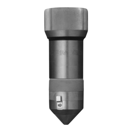
- Page 1 NERTAJET TORCH CPM 400 - 450 CPM 600 SAFETY INSTRUCTIONS FOR USE AND MAINTENANCE N° W000275368 - W000372096 - W000372852 8695 4598 EDITION : EN Instructions for use REF: REVISION DATE : 10-2018 Original instructions...
- Page 2 Thank for the trust you have expressed by purchasing this equipment, which will give you full satisfaction if you follow its instructions for use and maintenance. Its design, component specifications and workmanship comply with applicable European directives. Please refer to the enclosed CE declaration to identify the directives applicable to it.
-
Page 3: Table Of Contents
8695 4598 CONTENTS A - SAFETY INSTRUCTIONS ......................1 B - DESCRIPTION ..........................4 1 - GENERAL ........................... 4 2 - CHARACTERISTICS ......................4 C - DESCRIPTION OF ASSEMBLING IN PLASMA CUTTING PROCESS ........8 1 - CPM 400 : DOUBLE-FLUX OXYGEN ASSEMBLY « 30-130A » STRAIGHT CUT ..8 2 - CPM 400 : DOUBLE-FLUX OXYGEN ASSEMBLY «... - Page 4 8695 4598 REVISIONS REVISION B 04/10 DESIGNATION PAGE Complete update REVISION C 03/12 DESIGNATION PAGE - Complete update - Adding CPM300 REVISION D 10/12 DESIGNATION PAGE - Complete update REVISION E 05/14 DESIGNATION PAGE - Complete update « CPM600wi » « HPi » REVISION F 06/15 DESIGNATION...
-
Page 5: A - Safety Instructions
8695 4598 / G A - SAFETY INSTRUCTIONS For general safety instructions, please refer to the specific manual supplied with the equipment. EQUIPMENT FOR PLASMA CUTTING Before any servicing operations on the torch, make sure that the generator is powered down. During the cutting operation, the tip of the torch may be heated considerably. - Page 6 A - SAFETY INSTRUCTIONS 8695 4598 / G DISCHARGING FREEZCOOL « Red » « Green » W000010167 (9.6L) W000010168 (20L) W000381407 (20L) (pink heat transfer liquid 285) Freezcool should not be discharged in large You should inform them of : quantities into the natural environment.
- Page 7 A - SAFETY INSTRUCTIONS 8695 4598 / G CPM 400-450-600wi...
-
Page 8: B - Description
8695 4598 / G B - DESCRIPTION 1 - GENERAL The CPM 400-450-600 torch is a plasma cutting tool that is necessarily mechanised and designed to be coupled with a NERTAJET HP installation. In a CPM400-450-600wi torch an electrode is inserted with a shape suitable for plasmagene gas, selected according to the application. - Page 9 B - DESCRIPTION 8695 4598 / G Fluids: Flow Supply Service (max. use) Type Purity pressure pressure 150A 300A 450A l/min - Plasma pilot Argon 1 to 6 99.998% - Plasma marking - Plasma cutting Oxygen 0.5 to 7.5 99.5% - Plasma shield - Plasma...
- Page 10 B - DESCRIPTION 8695 4598 / G Torch cooling: To cool the plasma cutting torches in closed circuit with the FRIOJET, the following coolants may be used : - either Freezcool - or distilled water Special Freezcool liquid « Red » W000010167 - 9.6l can W000010168...
- Page 11 B - DESCRIPTION 8695 4598 / G Process cases: CPM400 ASSEMBLY Nertajet HP150 (30 to 130 A) case W000374198 30 - 50 - 80 - 100 - 130 Nertajet HP300 (200 & 260 A) drawer 200 - 260 W000374317 complement Nertajet HP450 (400A) drawer complement W000374318 Nertajet HP300 Bevel case...
-
Page 12: C - Description Of Assembling In Plasma Cutting Process
8695 4598 / G C - DESCRIPTION OF ASSEMBLING IN PLASMA CUTTING PROCESS 1 - CPM 400 : DOUBLE-FLUX OXYGEN ASSEMBLY « 30-130A » STRAIGHT CUT CPM 400-450-600wi... - Page 13 C - DESCRIPTION OF ASSEMBLING IN PLASMA CUTTING PROCESS 8695 4598 / G Straight cut assembly CPM400 « 30 - 130A » Reference Part no. Description Symbol Torch tip CPM400 and its keys (W000275438 and W000372624) W000373985 W000275464 Torch seal W000372925 Seal, 6.75x1.78 Nitrile Dust seal, CPM400...
-
Page 14: Cpm 400 : Double-Flux Oxygen Assembly " 200-260A " Straight Cut
C - DESCRIPTION OF ASSEMBLING IN PLASMA CUTTING PROCESS 8695 4598 / G 2 - CPM 400 : DOUBLE-FLUX OXYGEN ASSEMBLY « 200-260A » STRAIGHT CUT CPM 400-450-600wi C-10... - Page 15 C - DESCRIPTION OF ASSEMBLING IN PLASMA CUTTING PROCESS 8695 4598 / G Straight cut assembly CPM400 « 200 - 260A » Reference Part no. Description Symbol Torch tip CPM400 and its keys (W000275438 and W000372624) W000373985 W000275464 Torch seal W000372925 Seal, 6.75x1.78 Nitrile Dust seal, CPM400...
-
Page 16: 3 - Cpm 400 : Double Flux Oxygen Assembly « 130-260-400A » Straight Cut And Bevel
C - DESCRIPTION OF ASSEMBLING IN PLASMA CUTTING PROCESS 8695 4598 / G 3 - CPM 400 : DOUBLE FLUX OXYGEN ASSEMBLY « 130-260-400A » STRAIGHT CUT AND BEVEL CPM 400-450-600wi C-12... - Page 17 C - DESCRIPTION OF ASSEMBLING IN PLASMA CUTTING PROCESS 8695 4598 / G Straight cut and bevel assembly CPM400 « 130 - 260 - 400A » Reference Part no. Description Symbol Torch tip CPM400 and its keys (W000275438 and W000372624) W000373985 W000275464 Torch seal...
-
Page 18: Cpm 400 : Double-Flux Stainless Steel/Aluminium Assembly " 45-90-200A " Straight Cut
C - DESCRIPTION OF ASSEMBLING IN PLASMA CUTTING PROCESS 8695 4598 / G 4 - CPM 400 : DOUBLE-FLUX STAINLESS STEEL/ALUMINIUM ASSEMBLY « 45-90-200A » STRAIGHT CUT CPM 400-450-600wi C-14... - Page 19 C - DESCRIPTION OF ASSEMBLING IN PLASMA CUTTING PROCESS 8695 4598 / G Straight cut assembly CPM400 « 45 - 90 - 200A » : Stainless steel and aluminium Reference Part no. Description Symbol CPM400 torch tip and its keys (W000275438 and W000372624) W000373985 W000275464 Torch seal...
-
Page 20: Cpm 400 : Double Flux Stainless Steel/Aluminium Assembly " 130-260-400A " Straight And Bevel Cut
C - DESCRIPTION OF ASSEMBLING IN PLASMA CUTTING PROCESS 8695 4598 / G 5 - CPM 400 : DOUBLE FLUX STAINLESS STEEL/ALUMINIUM ASSEMBLY « 130-260-400A » STRAIGHT AND BEVEL CUT CPM 400-450-600wi C-16... - Page 21 C - DESCRIPTION OF ASSEMBLING IN PLASMA CUTTING PROCESS 8695 4598 / G Straight and bevel cut assembly CPM400 « 130 - 260 - 400A » : Stainless steel and aluminium Reference Part no. Description Symbol CPM400 torch tip and its keys (W000275438 and W000372624) W000373985 W000275464 Torch seal...
-
Page 22: Cpm 450 : Double Flux Nitrogen Or Argon Hydrogen Assembly " 20-120A " Straight Cut And Bevel
C - DESCRIPTION OF ASSEMBLING IN PLASMA CUTTING PROCESS 8695 4598 / G 6 - CPM 450 : DOUBLE FLUX NITROGEN OR ARGON HYDROGEN ASSEMBLY « 20-120A » STRAIGHT CUT AND BEVEL CPM 400-450-600wi C-18... - Page 23 C - DESCRIPTION OF ASSEMBLING IN PLASMA CUTTING PROCESS 8695 4598 / G CPM450 assembly « 20 - 120A » Reference Part no. Description Symbol Torch tip CPM450 W000275670 Z04092188 5 seals 37.4x1.78 Nitrile W000372925 Seal, 6.75x1.78 Nitrile Protective ring CPM450 W000372168 Immersion pipe CPM450 «...
-
Page 24: Cpm 450 : Double Flux Nitrogen Or Argon Hydrogen Assembly " 200A" And " 280-400A" Straight Cut And Bevel
C - DESCRIPTION OF ASSEMBLING IN PLASMA CUTTING PROCESS 8695 4598 / G 7 - CPM 450 : DOUBLE FLUX NITROGEN OR ARGON HYDROGEN ASSEMBLY « 200A» AND « 280-400A» STRAIGHT CUT AND BEVEL CPM 400-450-600wi C-20... - Page 25 C - DESCRIPTION OF ASSEMBLING IN PLASMA CUTTING PROCESS 8695 4598 / G CPM450 assembly « 200A » Reference Part no. Description Symbol Torch tip CPM450 W000275670 Z04092188 5 seals, 37.4x1.78 Nitrile W000372925 Seal, 6.75x1.78 Nitrile Protective ring CPM450 W000372168 Immersion pipe CPM450 «...
-
Page 26: Tooling Kit For Cpm450
C - DESCRIPTION OF ASSEMBLING IN PLASMA CUTTING PROCESS 8695 4598 / G 8 - TOOLING KIT FOR CPM 450 Tooling kit for CPM450 Reference Part no. Description Symbol Tool kit for CPM450 W000277951 Diffuser and electrode clamping extractor Insulating ring extraction pliers Nozzle extraction pliers Internal cap extraction ring H3 hex key for immersion pipe... - Page 27 C - DESCRIPTION OF ASSEMBLING IN PLASMA CUTTING PROCESS 8695 4598 / G CPM 400-450-600wi C-23...
-
Page 28: Cpm600 Wi : Water Vortex Nitrogen Assembly " 60-120A
C - DESCRIPTION OF ASSEMBLING IN PLASMA CUTTING PROCESS 8695 4598 / G 9 - CPM600 : WATER VORTEX NITROGEN ASSEMBLY « 60-120A » CPM 400-450-600wi C-24... - Page 29 C - DESCRIPTION OF ASSEMBLING IN PLASMA CUTTING PROCESS 8695 4598 / G CPM600 water vortex nitrogen assembly « 60-120A » Reference Part no. Description Symbol Torch tip CPM600 W000372584 W000325027 5 seals, 24x2 Nitrile Z04092198 5 seals, 46x2 Nitrile Z04092188 5 seals, 37.4x1.78 Nitrile W000372925...
-
Page 30: Cpm600 Wi : Water Vortex Nitrogen Assembly " 180-300A
C - DESCRIPTION OF ASSEMBLING IN PLASMA CUTTING PROCESS 8695 4598 / G 10 - CPM600 : WATER VORTEX NITROGEN ASSEMBLY « 180-300A » Pc7-2 CPM 400-450-600wi C-26... -
Page 31: Cpm600
C - DESCRIPTION OF ASSEMBLING IN PLASMA CUTTING PROCESS 8695 4598 / G CPM600 water vortex nitrogen assembly « 180-300A » Reference Part no. Description Symbol Torch tip CPM600 W000372584 W000325027 5 seals, 24x2 Nitrile Z04092198 5 seals, 46x2 Nitrile Z04092188 5 seals, 37.4x1.78 Nitrile W000372925... -
Page 32: Wi : Water Vortex Nitrogen Assembly " 300-600A
C - DESCRIPTION OF ASSEMBLING IN PLASMA CUTTING PROCESS 8695 4598 / G 11 - CPM 600 : WATER VORTEX NITROGEN ASSEMBLY « 300-600A » CPM 400-450-600wi C-28... - Page 33 C - DESCRIPTION OF ASSEMBLING IN PLASMA CUTTING PROCESS 8695 4598 / G CPM600 water vortex nitrogen assembly « 300-600A » Reference Part no. Description Symbol CPM600 W000372584 torch tip W000325027 5 nitrile seals, 24x2 Z04092198 5 nitrile seals, 46x2 Z04092188 5 nitrile seals, 37.4x1.78 W000372925...
-
Page 34: Torch Assembly Procedure For Cpm 400
C - DESCRIPTION OF ASSEMBLING IN PLASMA CUTTING PROCESS 8695 4598 / G 12 - TORCH ASSEMBLY PROCEDURE FOR CPM 400 1 - Clean the nozzle face and the inside of the torch with a dry cloth : Check the fastening of the immersion pipe (M10) to the body of the torch (M1) using an Allen key. 2 - Assemble the electrode ... - Page 35 C - DESCRIPTION OF ASSEMBLING IN PLASMA CUTTING PROCESS 8695 4598 / G 3 - Assemble the nozzle and the gas diffuser : Slightly lubricate the nozzle seals with silicone grease (M8). Never apply grease on the gas diffuser. ...
- Page 36 C - DESCRIPTION OF ASSEMBLING IN PLASMA CUTTING PROCESS 8695 4598 / G 4 - Assemble the internal cap : Slightly lubricate the two black seals of the tip of the CPM400 torch with silicone grease (M8). Fit the intermediate cap and screw it on tightly 5 - Assemble the downstream nozzle : ...
- Page 37 C - DESCRIPTION OF ASSEMBLING IN PLASMA CUTTING PROCESS 8695 4598 / G 6 - Assemble the external cap : Slightly lubricate the black seal of the external cap with silicone grease (M8). Moderately tighten the external cap on the tip of the torch. The downstream nozzle must no longer move, neither sideways nor up and down.
-
Page 38: Torch Assembly Procedure For Cpm 450
C - DESCRIPTION OF ASSEMBLING IN PLASMA CUTTING PROCESS 8695 4598 / G 13 - TORCH ASSEMBLY PROCEDURE FOR CPM 450 Clean the nozzle face and the inside of the torch with a dry cloth : CPM 400-450-600wi C-34... - Page 39 C - DESCRIPTION OF ASSEMBLING IN PLASMA CUTTING PROCESS 8695 4598 / G There are three possibilities for assembling consumables on the CPM450 torch for cutting stainless steel. 1. 20 to 120 A 2. 200 A 3. 280 to 400 A Continue as follows to install the consumables in the torch.
- Page 40 C - DESCRIPTION OF ASSEMBLING IN PLASMA CUTTING PROCESS 8695 4598 / G 1 - 20 to 120 A: Description of consumables : 20 - 200A immersion pipe 20-120A electrode 20-120 A diffuser 20 A nozzle 40 A nozzle 60 A nozzle 90 A nozzle 120 A nozzle 20 -120A insulating ring...
- Page 41 C - DESCRIPTION OF ASSEMBLING IN PLASMA CUTTING PROCESS 8695 4598 / G Assembling the consumables : Install the M18 electrode using an 11-mm socket spanner : Fit the gas diffuser in the nozzle and press it till the seal is no longer visible : ...
- Page 42 C - DESCRIPTION OF ASSEMBLING IN PLASMA CUTTING PROCESS 8695 4598 / G Fit the nozzle and press it till the seal is no longer visible. Tighten the external cap on the body of the torch The CPM 450 torch is ready for use. Removing the consumables : Special equipment is required for dismantling the torch.
- Page 43 C - DESCRIPTION OF ASSEMBLING IN PLASMA CUTTING PROCESS 8695 4598 / G 2 - 200 A Description of consumables : 40-200A immersion pipe 200A electrode 200 A diffuser 200 A nozzle 200 A internal cap 200 A downstream diffuser 200 A downstream nozzle 200 A external cap CPM 400-450-600wi...
- Page 44 C - DESCRIPTION OF ASSEMBLING IN PLASMA CUTTING PROCESS 8695 4598 / G Assembling the consumables Install the electrode using an 11-mm socket spanner : Fit the gas diffuser in the nozzle and press it till the seal is no longer visible : ...
- Page 45 C - DESCRIPTION OF ASSEMBLING IN PLASMA CUTTING PROCESS 8695 4598 / G Tighten the external cap on the body of the torch The CPM 450 torch is ready for use. Removing the consumables : Special equipment is required for dismantling the torch. Internal cap Nozzle CPM 400-450-600wi...
- Page 46 C - DESCRIPTION OF ASSEMBLING IN PLASMA CUTTING PROCESS 8695 4598 / G 3 - 280 to 400 A: Description of consumables : 280-400A immersion pipe 280A electrode 280-400 A upstream diffuser 280-400 A intermediate cap 280 A nozzle 280 A downstream diffuser 280 A downstream nozzle 280-400 A external cap CPM 400-450-600wi...
- Page 47 C - DESCRIPTION OF ASSEMBLING IN PLASMA CUTTING PROCESS 8695 4598 / G Assembling the consumables Install the electrode using an 11-mm socket spanner, then the upstream diffuser : Fit the intermediate cap in the nozzle : Fit the assembly in the body of the torch till the seal is no longer visible : ...
- Page 48 C - DESCRIPTION OF ASSEMBLING IN PLASMA CUTTING PROCESS 8695 4598 / G Tighten the external cap on the body of the torch The CPM 450 torch is ready for use. Removing the consumables : Special equipment is required for dismantling the torch Internal cap ring CPM 400-450-600wi C-44...
- Page 49 C - DESCRIPTION OF ASSEMBLING IN PLASMA CUTTING PROCESS 8695 4598 / G CPM 400-450-600wi C-45...
-
Page 50: Procedure For Assembling The Torch Cpm600
C - DESCRIPTION OF ASSEMBLING IN PLASMA CUTTING PROCESS 8695 4598 / G 14 - PROCEDURE FOR ASSEMBLING THE TORCH CPM600 Torch body maintenance: For optimised cutting performance, the nozzle holder, electrode holder and torch body must be clean (free of dust and metal particles, coolant or grease). Use a blower or a clean dry cloth to clean the surfaces. - Page 51 C - DESCRIPTION OF ASSEMBLING IN PLASMA CUTTING PROCESS 8695 4598 / G There are two possibilities for assembling consumables on the torch CPM600 1. from 60 to 240 A 2. 300 A and more, type W4 from 60 to 240 A 300 A and more, type W4 Proceed in the following order to fit the torch with the consumables defined in the cutting tables.
- Page 52 C - DESCRIPTION OF ASSEMBLING IN PLASMA CUTTING PROCESS 8695 4598 / G 1 - from 60 to 240 A: Description of consumables : Immersion pipe CPM600 Electrode W2 Straight gas diffuser « 60 à 240A » Plasma nozzle for use at « 60A » 90-Ø1.3 Plasma nozzle for use at «...
- Page 53 C - DESCRIPTION OF ASSEMBLING IN PLASMA CUTTING PROCESS 8695 4598 / G Assembling the consumables: Lubricate the 2 electrode seals (M56): Screw the electrode in the body, then moderately tighten using a 12-mm box spanner: Put the diffuser (M57) in place in the torch tip, with its 18.5 x 1.2 seal: GREASE-FREE ASSEMBLY CPM 400-450-600wi C-49...
- Page 54 C - DESCRIPTION OF ASSEMBLING IN PLASMA CUTTING PROCESS 8695 4598 / G Put the upstream nozzle (M62) in the torch tip, after selecting it according to the cutting table, and lubricate it above the outer diameter. Put the internal water vortex kit, CPM600 ...
- Page 55 C - DESCRIPTION OF ASSEMBLING IN PLASMA CUTTING PROCESS 8695 4598 / G Put in place the downstream nozzle (M65) (according to the cutting table) in the water vortex kit (M63). The seal need not be lubricated. Screw the nut (M66) that holds the downstream nozzle (M65) on the water vortex kit (M63). The seal need not be lubricated.
- Page 56 C - DESCRIPTION OF ASSEMBLING IN PLASMA CUTTING PROCESS 8695 4598 / G 2 - 300 A and above, type W4: Assembling the consumables : Immersion pipe CPM600 Vortex support « 300A » and more Straight gas vortex « 300A » and more Electrode W4 Plasma nozzle for use at «...
- Page 57 C - DESCRIPTION OF ASSEMBLING IN PLASMA CUTTING PROCESS 8695 4598 / G Assembling the consumables : Put the 300A vortex support (M59) in place in the tip: Lubricate the two electrode seals (M61), Place the diffuser (M60) on the electrode (M61) then moderately tighten with a 12-mm box spanner. ...
-
Page 58: Bundle And Connector Cpm 400-450-600 Wi
C - DESCRIPTION OF ASSEMBLING IN PLASMA CUTTING PROCESS 8695 4598 / G 15 - BUNDLE AND CONNECTOR CPM 400-450-600 CPM 400-450-600wi C-54... - Page 59 C - DESCRIPTION OF ASSEMBLING IN PLASMA CUTTING PROCESS 8695 4598 / G Bundle and connector CPM400-450-600 Reference Part no. Description Symbol Torch CPM400-450-600 (connector + bundle) 2.5 m. W000275368 Connectors compatible with BRT400-450 Torch CPM400-450-600wi (connector + bundle) 3.9 m. W000372096 Connectors compatible with BRT400-450 Torch CPM400-450-600wi (connector + bundle) 2.5 m R360.
-
Page 60: D - Torch Lead-Bundles
8695 4598 / G D - TORCH LEAD-BUNDLES 1 - CONNECTING THE BUNDLES NEAR THE CPM400-450-600 TORCH CPM 400-450-600wi D-56... - Page 61 D - TORCH LEAD-BUNDLES 8695 4598 / G Mark Designation Annular gas Cooling circuit inlet + current supply Vortex Cutting gas (to reference 8) Cooling circuit return + current supply Nozzle cable Plate detection (for connection on the torch body) EV block not embeded N°...
-
Page 62: Connecting The Bundles Near The Hf 400 Unit
D - TORCH LEAD-BUNDLES 8695 4598 / G 2 - CONNECTING THE BUNDLES NEAR THE HF 400 UNIT Mark Designation Plate detection Pilot gas Annular gas Cutting gas Vortex (optional) Torch nozzle cable Cooling water circuit return Cooling water circuit outlet CPM 400-450-600wi D-58... -
Page 63: E - Upkeep And Maintenance
8695 4598 / G E - UPKEEP AND MAINTENANCE Before any servicing operations on the torch, make sure that the generator is powered down. During the cutting operation, the tip of the torch may be heated considerably. Before removal, it is imperative to use protective equipment. -
Page 64: Basic Rules To Follow For Cpm400-450-600
E - UPKEEP AND MAINTENANCE 8695 4598 / G REMARKS : - when the electrode is removed, be careful not to damage the end of the dipping tube located in the torch body, - check regularly that the dipping tube is properly tightened before refitting the electrode. -
Page 65: Trouble Shooting
E - UPKEEP AND MAINTENANCE 8695 4598 / G 3 - TROUBLE SHOOTING DEFECTS SOLUTIONS Pilot arcing difficult - Check the type, pressure and flowrate of pilot gas according to the scales. - Check that there is sparking of the H.F between the electrode and the nozzle. - Page 66 E - UPKEEP AND MAINTENANCE 8695 4598 / G DEFECTS SOLUTIONS Destruction of the nozzle - The destruction of a nozzle can be caused by : - a power increase which is too quick : increase the power run-up time-delay, - contact with the part due to a metal projection during arcing in middle of sheet metal: raise the torch at time of transfer, - direct contact with the part,...
-
Page 67: Spare Parts
E - UPKEEP AND MAINTENANCE 8695 4598 / G 4 - SPARE PARTS Spare parts relating to the consumables of the torch CPM400-450-600 can be found in section : « C - Description of assembling in plasma cutting process » ... -
Page 68: Personal Notes
E - UPKEEP AND MAINTENANCE 8695 4598 / G PERSONAL NOTES Lincoln Electric France S.A.S. Avenue Franklin Roosevelt 76120 Le Grand Quevilly 76121 Le Grand Quevilly cedex www.lincolnelectriceurope.com CPM 400-450-600wi E-64...
Need help?
Do you have a question about the NERTAJET CPM 400 and is the answer not in the manual?
Questions and answers