Table of Contents
Advertisement
Available languages
Available languages
Quick Links
Einbau- und Betriebsanleitung
Einbau- und Betriebsanleitung
DE
DE
Einbau- und Betriebsanleitung....................................................................... 2
Einbau- und Betriebsanleitung....................................................................... 2
EN
EN
Installation and operating instructions.......................................................... 18
Installation and operating instructions.......................................................... 18
FR
FR
Instructions de pose et d'utilisation.............................................................. 34
Instructions de pose et d'utilisation.............................................................. 34
IT
IT
Istruzioni per l'installazione e l'uso...............................................................51
Istruzioni per l'installazione e l'uso...............................................................51
NL
NL
Inbouw- en bedieningshandleiding............................................................... 68
Inbouw- en bedieningshandleiding............................................................... 68
PL
PL
Instrukcja zabudowy i obsługi.......................................................................85
Instrukcja zabudowy i obsługi.......................................................................85
2022/11
Aquapump Medium
Aquapump Medium
LW 600
LW 600
328-198_04
Advertisement
Chapters
Table of Contents

Related Manuals for Kessel LW 600


Summary of Contents for Kessel LW 600
- Page 1 Aquapump Medium Aquapump Medium LW 600 LW 600 Einbau- und Betriebsanleitung Einbau- und Betriebsanleitung Einbau- und Betriebsanleitung............... 2 Einbau- und Betriebsanleitung............... 2 Installation and operating instructions............18 Installation and operating instructions............18 Instructions de pose et d’utilisation.............. 34 Instructions de pose et d’utilisation.............. 34 Istruzioni per l’installazione e l’uso...............51...
-
Page 2: Table Of Contents
Inhalt Hinweise zu dieser Anleitung........................... Sicherheit.................................. Technische Daten..............................Montage..................................Inbetriebnahme................................. Wartung..................................009-065_DOP_Pumpstation_Aquapump_Medium....................102 009-065-C_DOC_Pumpstation_Aquapump_Medium....................103 009-072_DOP_Pumpstation_Aquapump_Medium....................104 009-072-C_DOC_Pumpstation_Aquapump_Medium....................105 2 / 108 Einbau- und Betriebsanleitung 328-198_03... - Page 3 Liebe Kundin, lieber Kunde, als Premiumhersteller von innovativen Produkten für die Entwässerungstechnik bietet KESSEL ganzheitliche Systemlösun- gen und kundenorientierten Service. Dabei stellen wir höchste Qualitätsstandards und setzen konsequent auf Nachhaltig- keit - nicht nur bei der Herstellung unserer Produkte, sondern auch im Hinblick auf deren langfristigen Betrieb setzen wir uns dafür ein, dass Sie und Ihr Eigentum dauerhaft geschützt sind.
-
Page 4: Hinweise Zu Dieser Anleitung
Hinweise zu dieser Anleitung Folgende Darstellungskonventionen erleichtern die Orientierung: Darstellung Erläuterung Positionsnummer 5 von nebenstehender Abbildung Handlungsschritt in Abbildung Prüfen, ob Handsteuerung aktiviert wurde. Handlungsvoraussetzung OK betätigen. Handlungsschritt Anlage ist betriebsbereit. Handlungsergebnis Querverweis auf Kapitel 2 siehe "Sicherheit", Seite 5 Bildschirmtext |Wartungsintervall definieren| Fettdruck... -
Page 5: Sicherheit
Sicherheit Folgende Symbole werden verwendet: Zeichen Bedeutung Gerät freischalten! Gebrauchsanweisung beachten CE-Kennzeichnung Warnung Elektrizität WEEE-Symbol, Produkt unterliegt RoHS-Richtlinie Warnt vor einer Gefährdung von Personen. Eine Missachtung dieses Hinweises kann schwerste Verletzungen oder Tod zur Folge haben. WARNUNG Warnt vor einer Gefährdung von Personen und Material. Eine Missachtung dieses Hinweises kann schwere Verletzungen und Materialschäden zur Folge haben. - Page 6 Vorgeschriebene persönliche Schutzausrüstung! Bei Einbau, Wartung und Entsorgung an der Anlage stets Schutzausrüstung verwenden. Schutzkleidung Schutzhandschuhe Sicherheitsschuhe Gesichtsschutz VORSICHT Pumpen können unerwartet anlaufen. Vor Wartung oder Reparatur die Anlage ausschalten oder von der Stromversorgung trennen. Die Pumpe darf niemals trocken oder im Schlürfbetrieb laufen, Freistromrad und Pumpengehäuse müssen immer bis zur Mindesteintauchtiefe überflutet sein.
- Page 7 Der Betreiber der Anlage ist dazu verpflichtet: eine Gefährdungsbeurteilung zu erstellen, entsprechende Gefährdungszonen zu ermitteln und auszuweisen, Sicherheitsunterweisungen durchzuführen, gegen die Benutzung durch Unbefugte zu sichern. Person freigegebene Tätigkeiten an KESSEL-Anlagen Betreiber Sichtprüfung, Batterietausch Sachkundiger (kennt, ver- Entleerung, Reinigung steht Betriebsanweisung)
- Page 8 Bestimmungsgemäße Verwendung Die Anlage ist als Mono-Anlage mit einer Pumpe für den Einsatz bei Einfamilienhäusern und als Duo-Anlage für den Einsatz bei Mehrfamilienhäusern, gewerblichen Objekten und Einrichtungen der Öffentlichen Hand einzusetzen. Als Fördermedium sind ausschließlich häusliche Abwässer möglich. Wird die Anlage für fäkalienhaltiges Abwasser einge- setzt, muss auch die entsprechende Pumpenvariante (hier STZ 1000 - Schwarzwasser-Tauchpumpe mit Zerhacker) mon- tiert werden.
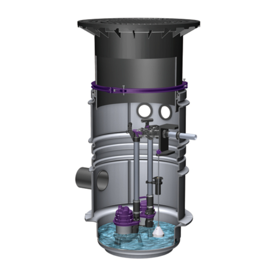
- Page 9 Pumpe(n) für fäkalienfreies Abwasser GTF 600 oder GTF 1200 Pumpe(n) für fäkalienhaltiges Abwasser STZ 1000 (keine ATEX-Eignung) Einbautiefen T1, T2, T3 Eine bzw. zwei Pumpen Schachtsystem LW 600 Zulauf (DN 100 bei Pumpentyp KTP 500/ DN 150 bei GTF 1200) Anschluss Entlüftungsleitung (DN 100) Abdeckplatte Teleskopisches Aufsatzstück...
- Page 10 10 / 108 Einbau- und Betriebsanleitung 328-198_04...
-
Page 11: Technische Daten
Technische Daten Angabe / Pumpenart GTF 600 GTF 1200 STZ 1000 Gewicht 7 kg 10 kg 10 kg Leistung P1 / P2 500 W / 320 W 1400 W /840 W 1200 W / 690 W Drehzahl 2800 min-1 2650 min-1 2800 min-1 Betriebsspannung 230 V;... - Page 12 Maße und Gewichte Pumpe mit Schwim- GTF 600 Pumpe für Schaltgerät 2 Pumpen für Schaltgerät merschalter Einbautiefe Art. Nr. Gewicht (kg*) Art. Nr. Gewicht (kg*) Art. Nr. Gewicht (kg*) T in mm Klasse A/B, D A/B, D Klasse A/B, D A/B, D Klasse A/B, D A/B, D...
-
Page 13: Montage
Montage Bodenaushub VORSICHT Statik für Verkehrssicherheit beachten. Schachtverbau für Lastklasse D kann eine Last- verteilplatte, Beton: 0,18m x 2,3m x 2,3m (Stärke x Höhe x Breite) erforderlich machen. Erforderliche Lastklasse und Statik gemäß Umgebung/Nutzungsbedingungen ermitteln. Standardstraßenaufbau gemäß Richtlinien für Anlage von Straßen einhalten. Eignung von Produkt(-variante) für Umgebungsbedingun- gen (siehe "Bestimmungsgemäße Verwendung", Seite 8) und Einbautiefe (siehe "Produktbeschreibung", Seite 9) - Page 14 Schachteinbau Schacht einsetzen und waagrecht ausrichten. Bei Bedarf Schacht mit Magerbeton vertikal fixieren. Bei Grundwasser den Schacht mit Beton gegen Auftrieb sichern. Verbleibenden Zwischenraum (siehe "Abb. 1: Bodenaushub", Seite 13) abschnittsweise mit 0/16 Füllmaterial verfüllen. Nach 30 cm jeweils auf Dpr = 97% verdichten, bis Höhe Bodenkante oder Standard-Straßenaufbau. Rohranschluss Zulaufleitung anschließen (Gefälle beachten, ggf.
- Page 15 Niveauerfassung montieren Anlagen, deren Niveauerfassung mit Schwimmerschal- ter ausgeführt ist, verfügen nicht über Schaltgeräte und Alarmsonde. In diesem Fall entsprechende Handlungs- schritte ignorieren. Alarmsonde an folgende Position montieren: T1 - Schutzrohr an waagrechte Halterung anklipsen. T2/T3 - Schutzrohr an Steigleitung anklipsen. Alarmsonde in Schutzrohr einschrauben, Leitung durch Kabelleerrohr führen.
-
Page 16: Inbetriebnahme
Inbetriebnahme Für die Inbetriebnahme ist die EN 12056-4 zu beachten. Prüfung der Anlage Bei Schwarzwasserbetrieb darf die Pumpe nur so eingesetzt werden, dass kein Lufteintritt ins Pumpengehäuse möglich ist. Der Lauf der Pumpen ohne Wasser führt zu erhöhtem Verschleiß und möglicher Funkenbildung. Vor Inbetriebnahme sind folgende Punkte zu prüfen: Korrekter Einbau der Pumpe Fixierung aller entnehmbaren Bauteile... -
Page 17: Wartung
Einhandverschluss öffnen. Steigleitung komplett mit Pumpe am Haltegriff herauszie- hen. Pumpenteile auf Verformung und Ablagerungen prüfen, ggf. KESSEL-Service kontaktieren. Leichtgängigkeit der beweglichen Teile sicherstellen. Alarmsonde herausziehen. Schutzrohr abklipsen, ggf. beides in Wasserbad reinigen. Tauchglocke herausziehen und mit Wasser reinigen. - Page 18 Contents Notes on this manual............................... Safety..................................Technical data................................Installation................................. Commissioning................................. Maintenance................................18 / 108 Installation and operating instructions 328-198_03...
- Page 19 Dear Customer, As a premium manufacturer of innovative products for draining technology, KESSEL offers integrated system solutions and customer-oriented service. In doing so, we set the highest quality standards and focus firmly on sustainability - not only with the manufacturing of our products, but also with regard to their long-term operation and we strive to ensure that you and your property are protected over the long term.
-
Page 20: Notes On This Manual
Notes on this manual The following conventions make it easier to navigate the manual: Symbol Explanation Position number 5 from the adjacent figure Action step in figure Check whether manual control has been Prerequisite for action activated. Press OK. Action step System is ready for operation. -
Page 21: Safety
Safety The following symbols are used: Icon Meaning Isolate device! Observe the instructions for use CE marking Warning, electricity WEEE icon, product governed by RoHS Guideline Warns of a hazard for persons. Ignoring this warning can lead to serious injuries or death. WARNING Warns of a hazard for persons and material. - Page 22 Prescribed personal protective equipment! Always use personal protective equipment during installation, maintenance and disposal work on the system. Protective clothing Protective gloves Safety footwear Face protection CAUTION Pumps can start up unexpectedly. Before undertaking maintenance or repair work on the system, switch it off or disconnect it from the power supply. The pump must never run dry or in slurping operation;...
- Page 23 Person Approved activities on KESSEL systems Operating company Visual check, inspec- tion, change of battery Technical expert, (familiar with, Emptying, cleaning...
- Page 24 Intended use The system is to be used as a Mono system with one pump in single-family homes and as a Duo system in multi-family homes, industrial buildings and public facilities. Domestic wastewater is the only pumping medium possible. If the system is used for faecal wastewater, the corresponding pump variant (here STZ 1000) must also be installed.
- Page 25 Pump(s) for wastewater containing sewage STZ 1000 (not suitable for ATEX) Installation depths D1, D2, D3 One or two pumps Chamber system LW 600 Inlet (DN 100 for pump type KTP 500/DN 150 for GTF 1200) Connection of ventilation pipe (DN 100)
- Page 26 26 / 108 Installation and operating instructions 328-198_03...
-
Page 27: Technical Data
Technical data Information / pump type GTF 600 GTF 1200 STZ 1000 Weight 7 kg 10 kg 10 kg Power P1 / P2 500 W / 320 W 1400 W /840 W 1200 W / 690 W Speed 2800 rpm 2650 rpm 2800 rpm Operating voltage... - Page 28 Dimensions and weights GTF 600 Pump with float switch Pump for control unit 2 pumps for control unit Installation depth Art. no. Weight (kg*) Art. no. Weight (kg*) Art. no. Weight (kg*) D in mm Class A/B, D A/B, D Class A/B, D A/B, D Class A/B, D...
-
Page 29: Installation
Installation Soil excavation CAUTION Note the structural calculations for traffic safety. Chamber installation for load class D may require a load distribution plate made of concrete: 0.18m x 2.3m x 2.3m (thickness x height x width). Determine the required load class and structural calculations in accordance with the environment / use conditions. - Page 30 Chamber installation Insert the chamber and align it horizontally. If necessary, fix the chamber in place vertically using lean concrete. When installed in groundwater, secure the chamber against buoyancy. Backfill the remaining space (see "Fig. 1: Soil excavation", page 29) in sections using 0/16 fill material. After every 30 cm compact to DPr = 97%, up to the height of the ground edge or standard road structure.
- Page 31 Installing the level measurement Systems that have float switches for level measurement do not have control units and an alarm probe. In this case, ignore the associated steps. Install the alarm probe in the following position: Clip the D1 protective tube onto the horizontal bracket. Clip the D2/D3 protective tube onto the riser pipe.
-
Page 32: Commissioning
Commissioning Observe EN 12056-4 for the commissioning. Checking the system During black water operation, the pump may only be used in such a way that no air can get into the pump housing. Run- ning the pump without water leads to increased wear and possible sparking. Check the following points before commissioning: Correct installation of the pump Fixing of all removable components... -
Page 33: Maintenance
Pull out the riser pipe complete with pump using the han- dle. Check the pump parts for deformation and deposits, con- tact KESSEL service department if necessary. Ensure the moving parts can move easily. Pull out the alarm probe. Unclip the protective tube, clean both in a water bath if necessary. - Page 34 Sommaire Informations spécifiques aux présentes instructions....................Sécurité..................................Caractéristiques techniques............................. Montage..................................Mise en service................................ Maintenance................................34 / 108 Instructions de pose et d’utilisation 328-198_03...
- Page 35 Chère cliente, cher client, En qualité de producteur de pointe de produits novateurs dans le domaine de la technique d’assainissement, KESSEL pro- pose des réponses systématiques globales et un service orienté aux besoins de la clientèle. Nous misons simultanément sur les normes de qualité les plus élevées et une durabilité conséquente – non seulement lors de la fabrication de nos pro- duits, mais également pour leur utilisation à...
-
Page 36: Informations Spécifiques Aux Présentes Instructions
Informations spécifiques aux présentes instructions Les conventions de représentation suivantes facilitent l’orientation : Représentation Explication Numéro de repère 5 de la figure ci-contre Action de la figure Vérifier si la commande manuelle a été acti- Condition de réalisation de l’action vée. -
Page 37: Sécurité
Sécurité Les instructions emploient les pictogrammes suivants : Pictogramme / label Signification Activer l’appareil ! Observer le mode d'emploi Label de conformité CE Mise en garde contre l’électricité Pictogramme DEEE, produit soumis à la directive RoHS Avertit d'un danger corporel. L’inobservation de cette mise en garde peut provoquer des blessures graves, voire mortelles. - Page 38 Équipement de protection personnel prescrit! Le port d’un équipement de protection est toujours imposé lors de la pose, de la maintenance et de l’évacuation du poste. Vêtements de protection Gants de protection Chaussures de sécurité Dispositif de protection du visage ATTENTION Les pompes peuvent démarrer de manière inopinée.
- Page 39 à risques s’y rapportant et d'attirer l’attention sur ces zones, de veiller à la mise en pratique de formations se rapportant aux consignes de sécurité, d’empêcher toute personne non autorisée de l’utiliser. Personne Activités autorisées sur les postes KESSEL Exploitant Contrôle visuel, remplacement de la batterie Technicien spécialisé...
- Page 40 Utilisation conforme à l'usage prévu Le poste doit être utilisé en tant que poste Mono avec une pompe pour une utilisation dans des maisons individuelles et en tant que poste Duo pour une utilisation dans des logements collectifs, des bâtiments commerciaux et des organismes publics.
- Page 41 Pompe(s) pour eaux vannes STZ 1000 (pas d'aptitude ATEX) Profondeurs de pose T1, T2, T3 Une ou deux pompes Système de regard LW 600 Arrivée (DN 100 pour type de pompe KTP 500/ DN 150 pour GTF 1200) Raccord de la conduite d'aéra-...
- Page 42 42 / 108 Instructions de pose et d’utilisation 328-198_03...
-
Page 43: Caractéristiques Techniques
Caractéristiques techniques Indication / type de pompe GTF 600 GTF 1200 STZ 1000 Poids 7 kg 10 kg 10 kg Puissance P1 / P2 500 W / 320 W 1400 W /840 W 1200 W / 690 W Régime 2800 min-1 2650 min-1 2800 min-1 Tension de service... - Page 44 GTF 1200/ Poste Mono/ GTF 600 STZ 1000 Duo avec ges- tionnaire SDS Mono Mono Volume utile [l] T1/T2/T3 Niveau d'acti- 185/200 185/200 vation [mm] Niveau d’alarme [mm] Niveau de 145/160 145/160 désactiva- tion [mm] Titre 44 / 108 Instructions de pose et d’utilisation 328-198_03...
- Page 45 Dimensions et poids Pompe avec inter- GTF 600 Pompe pour gestionnaire 2 pompes pour gestionnaire rupteur à flotteur Profondeur de Réf. Poids (kg*) Réf. Poids (kg*) Réf. Poids (kg*) pose Classe A/B, D A/B, D Classe A/B, D A/B, D Classe A/B, D A/B, D T en mm...
-
Page 46: Montage
Montage Excavation du sol ATTENTION Observer la statique de conformité à la sécurité routière. La pose du regard pour une classe de charge D peut imposer la mise en place d’une plaque de répartition de la charge, béton : 0,18 m x 2,3 m x 2,3 m (épaisseur x hauteur x largeur). - Page 47 Montage du module rehausse Mettre le module rehausse en place et l’installer horizontalement. Si nécessaire, fixer le module rehausse à la verticale via l’ajout de béton maigre. En cas de pose dans la nappe phréatique, sécuriser le module rehausse contre les poussées avec du béton. Remblayer l'espace intermédiaire résiduel, (cf.
- Page 48 Montage de la détection du niveau Les postes dotés d’un interrupteur à flotteur pour la détection du niveau n'ont pas de gestionnaire ni de sonde d'alarme. Dans un tel cas, ignorer les étapes correspon- dantes. Monter la sonde d'alarme à la position suivante : T1 - Clipser le tube de protection sur le support horizon- tal.
-
Page 49: Mise En Service
Mise en service La norme EN 12056-4 doit être respectée lors de la mise en service. Contrôle du poste Veillez à exclure toute entrée d'air dans le carter de la pompe en exploitation avec des eaux vannes. Le fonctionnement des pompes sans eau entraîne une usure accrue et une éventuelle formation d'étincelles. Vérifiez les points suivants avant la mise en service : Montage correct de la pompe Fixation de tous les éléments démontables... -
Page 50: Maintenance
Extraire entièrement la conduite ascendante avec la pompe au niveau de la poignée. Vérifier si les pièces de la pompe présentent des défor- mations et des dépôts. Au besoin, contacter le service KESSEL. S’assurer que les pièces mobiles se déplacent sans entrave. Extraire la sonde d'alarme. - Page 51 Indice Indicazioni sulle presenti istruzioni.......................... Sicurezza.................................. Dati tecnici................................Montaggio................................. Messa in funzione..............................Manutenzione................................328-198_03 Istruzioni per l’installazione e l’uso 51 / 108...
- Page 52 Cara cliente, caro cliente, in qualità di produttore premium di prodotti innovativi per la tecnica di drenaggio, KESSEL offre soluzioni di sistema integrate e un servizio orientato al cliente. Puntiamo sui massimi standard qualitativi e ci impegniamo coerentemente per la sosteni- bilità...
-
Page 53: Indicazioni Sulle Presenti Istruzioni
Indicazioni sulle presenti istruzioni Le seguenti convenzioni illustrative semplificano l’orientamento: Simbolo Spiegazione Posizione numero 5 della figura accanto Passaggio procedurale nella figura Controllare se il comando manuale è stato Presupposti per l’azione attivato. Premere OK. Passaggio procedurale L’impianto è pronto per funzionare. Risultato dell’azione vd. -
Page 54: Sicurezza
Sicurezza Sono impiegati i simboli seguenti: Simbolo Significato Mettere fuori tensione l’apparecchio! Prestare attenzione all’istruzione per l’uso Marchio CE Attenzione, elettricità Simbolo WEEE, prodotto soggetto alla direttiva RoHS Avverte circa un pericolo per le persone. La mancata osservanza di que- sta avvertenza può... - Page 55 Dispositivi di protezione individuale prescritti! In occasione dell’installazione, della manutenzione e dello smaltimento dell’impianto, impiegare sempre i disposi- tivi di protezione. Indumenti protettivi Guanti protettivi Calzature antinfortunistiche Protezione per il viso ATTENZIONE Le pompe possono avviarsi inaspettatamente. Prima della manutenzione o della riparazione, spegnere l’impianto o scollegarlo dall’alimentazione di corrente. La pompa non deve mai funzionare a vuoto o in funzionamento in risucchio, la girante libera e l’alloggiamento della pompa devono essere sempre sommersi fino alla profondità...
- Page 56 Persona Mansioni ammesse sugli impianti KESSEL Esercente Controllo visivo, sosti- tuzione della batteria Esperto (conosce e com- Svuotamento, puli- prende le istruzioni per l’uso)
- Page 57 Uso conforme alla destinazione L’impianto deve essere impiegato quale impianto Mono con una pompa per l’impiego nelle case unifamiliari e quale impianto Duo per l’impiego nelle case plurifamiliari, negli edifici commerciali e nelle strutture pubbliche. Il fluido trasportato può essere rappresentato esclusivamente dalle acque di scarico domestiche. Se l’impianto dovesse essere impiegato per le acque di scarico contenenti sostanze fecali, dovrà...
- Page 58 Pompa/e per le acque di scarico contenenti sostanze fecali STZ 1000 (priva di adeguatezza ATEX) Profondità di installazione P1, P2, P3 Una o due pompe Sistema di pozzetto LW 600 Entrata (DN 100 con le pompe del tipo KTP 500 / DN 150 con le pompe del tipo GTF 1200)
- Page 59 328-198_03 Istruzioni per l’installazione e l’uso 59 / 108...
-
Page 60: Dati Tecnici
Dati tecnici Indicazione / tipo di pompa GTF 600 GTF 1200 STZ 1000 Peso 7 kg 10 kg 10 kg Potenza P1 / P2 500 W / 320 W 1400 W / 840 W 1200 W / 690 W Numero di giri 2.800 min-1 2.650 min-1 2.800 min-1... - Page 61 Impianto GTF 1200/ GTF 600 Mono/Duo STZ 1000 con centra- Mono Mono lina SDS Volume di pompaggio [l] T1/T2/T3 Livello di 185/200 185/200 accen- sione [mm] Livello d’al- larme [mm] Livello di spe- 145/160 145/160 gnimento [mm] Titolo 328-198_03 Istruzioni per l’installazione e l’uso 61 / 108...
- Page 62 Misure e pesi Pompa con interrut- GTF 600 Pompa per centralina 2 pompe per centralina tore a galleggiante Profondità di Codice articolo Codice articolo Codice articolo Peso (kg*) Peso (kg*) Peso (kg*) installazione Classe di Classe di Classe di A/B, D A/B, D A/B, D P in mm...
-
Page 63: Montaggio
Montaggio Scavo nel terreno ATTENZIONE Tenere in considerazione la statica per la sicu- rezza della circolazione. L’installazione di un pozzetto per la classe di carico D può rendere necessaria una piastra di distribu- zione del carico di calcestruzzo: 0,18 m x 2,3 m x 2,3 m (spessore x altezza x larghezza). - Page 64 Installazione del pozzetto Posare il modulo del pozzetto e allinearlo in orizzontale. Se necessario, fissare verticalmente il modulo del pozzetto con calcestruzzo magro. In presenza di acqua freatica, assicurare il modulo del pozzetto contro il galleggiamento con calcestruzzo. Riempire lo spazio vuoto rimasto (vd. "fig. 1: Scavo nel terreno", pagina 63) a strati con materiale di riempimento 0/16. Compattare ogni 30 cm con gc = 97%, fino a raggiungere l’altezza del bordo superiore della costruzione stradale stan- dard.
- Page 65 Montaggio del rilevamento del livello Gli impianti il cui rilevamento del livello avviene tramite l’interruttore a galleggiante non dispongono di centraline e sonda di allarme. In questo caso, ignorare le relative istruzioni. Montare la sonda di allarme nella posizione seguente: P1 –...
-
Page 66: Messa In Funzione
Messa in funzione Per la messa in funzione deve essere rispettata la norma EN 12056-4. Controllo dell’impianto In caso di funzionamento con le acque nere, la pompa può essere impiegata solo in modo che nel corpo della pompa non sia possibile alcuna infiltrazione d’aria. La marcia della pompa senza acqua produce un’usura elevata e potrebbe pro- durre scintille. -
Page 67: Manutenzione
Estrarre completamente la colonna montante con la pompa dalla maniglia. Controllare la presenza di deformazioni e depositi sulle parti della pompa, eventualmente contattare il servizio KESSEL. Accertare la mobilità della parti mobili. Estrarre la sonda di allarme. Staccare il tubo di prote- zione, eventualmente lavare in un bagno d’acqua. - Page 68 Inhoud Informatie over deze handleiding..........................Veiligheid.................................. Technische gegevens............................... Monteren................................... Inbedrijfstelling................................Onderhoud................................68 / 108 Inbouw- en bedieningshandleiding 328-198_03...
- Page 69 Beste klant, Als premium fabrikant van innovatieve producten voor de afwateringstechniek biedt KESSEL totale systeemoplossingen en klantgerichte service. Wij stellen hierbij maximale kwaliteitsnormen en zetten consequent in op duurzaamheid, niet alleen bij de productie van onze producten, maar ook met het oog op hun langdurige gebruik zetten wij ons in voor een permanente bescherming van u en uw eigendom.
-
Page 70: Informatie Over Deze Handleiding
Informatie over deze handleiding De volgende weergaveconventies maken de oriëntatie eenvoudiger: Afbeelding Uitleg Positienummer 5 van nevenstaande afbeelding Handeling op de afbeelding … Controleren of de handbesturing is inge- Voorwaarde voor de handeling schakeld. Op OK drukken. Werkstap De installatie is bedrijfsklaar. Resultaat van de handeling zie "Veiligheid", pagina 71 Kruisverwijzing naar hoofdstuk 2... -
Page 71: Veiligheid
Veiligheid De volgende symbolen worden gebruikt: Teken Betekenis Apparaat vrijschakelen! Gebruiksaanwijzing in acht nemen CE-markering Waarschuwing elektriciteit WEEE-symbool, product is onderhevig aan RoHS-richtlijn Waarschuwt tegen gevaar voor personen. Het niet-naleven van deze aanwijzing kan zeer ernstig letsel of de dood tot gevolg hebben. WAARSCHUWING Waarschuwt tegen gevaar voor personen en materiaal. - Page 72 Voorgeschreven persoonlijke beschermingsmiddelen! Bij de inbouw, het onderhoud en lediging van de installatie altijd beschermingsmiddelen gebruiken. beschermende kleding Veiligheidshandschoenen Veiligheidsschoenen Gezichtsbescherming VOORZICHTIG Pompen kunnen onverwachts starten. Voordat u onderhoud pleegt of reparaties uitvoert, moet u de installatie uitschakelen of de stroomvoorziening onder- breken.
- Page 73 De exploitant van de installatie is verplicht tot: het maken van een risicobeoordeling, het vaststellen en aantonen van gevarenzones, het uitvoeren van veiligheidsinstructies, het beveiligen tegen gebruik door onbevoegden. Persoon Vrijgegeven werkzaamheden bij KESSEL-installaties Exploitant Visuele controle, batterij vervangen Deskundige (kent en Leging, reiniging...
- Page 74 Beoogd gebruik De installatie kan als mono-installatie met één pomp worden gebruikt voor eengezinswoningen en als duo-installatie worden gebruikt voor meergezinswoningen, commerciële en overheidsgebouwen. De pomp is alleen geschikt voor huishoudelijk afvalwater. Als de installatie voor fecaliënhoudend afvalwater moet worden gebruikt, moet ook de bijbehorende pompvariant (in dit geval de STZ 1000) worden gemonteerd.
- Page 75 Pomp(en) voor fecaliënvrij afvalwater GTF 600 of GTF 1200 Pomp(en) voor fecaliënhoudend afvalwater STZ 1000 (niet geschikt voor ATEX) Inbouwdiepten T1, T2, T3 Een of twee pompen Schachtsysteem LW 600 Toevoer (DN 100 voor pomptype KTP 500 of DN 150 voor pomptype GTF 1200) Aansluiting ontluchtingsleiding (DN 100)
- Page 76 76 / 108 Inbouw- en bedieningshandleiding 328-198_03...
-
Page 77: Technische Gegevens
Technische gegevens Informatie / soort pomp GTF 600 GTF 1200 STZ 1000 Gewicht 7 kg 10 kg 10 kg Vermogen P1 / P2 500 W / 320 W 1400 W / 840 W 1200 W / 690 W Toerental 2800 omw/min 2650 omw/min 2800 omw/min Bedrijfsspanning... - Page 78 Mono-/duo- GTF 1200 / GTF 600 installatie met STZ 1000 ZDS-bestu- Mono Mono ringskast Netto-inhoud [l] T1/T2/T3 Inschakelni- 185/200 185/200 veau [mm] Alarmni- veau [mm] Uitschakelni- 145/160 145/160 veau [mm] Titel 78 / 108 Inbouw- en bedieningshandleiding 328-198_03...
- Page 79 Maten en gewichten Twee pompen voor GTF 600 Pomp met vlotterschakelaar Pomp voor besturingskast besturingskast Inbouwdiepte Art.nr. Gewicht (kg*) Art.nr. Gewicht (kg*) Art.nr. Gewicht (kg*) T in mm Klasse A/B, D A/B, D Klasse A/B, D A/B, D Klasse A/B, D A/B, D T1 800 –...
-
Page 80: Monteren
Monteren Grond afgraven VOORZICHTIG Houd vanwege de verkeersveiligheid rekening met de statische belasting. Bij het dichten van schachten voor belastingsklasse D kan een betonnen lastverdeelplaat van 0,18 m x 2,3 m x 2,3 m (dikte x hoogte x breedte) noodzake- lijk zijn. - Page 81 De schacht monteren Plaats de schacht en lijn hem waterpas uit. Zet hem zo nodig met stampbeton vast. Zorg er bij grondwater met beton voor dat de schacht niet kan gaan drijven. Vul de resterende tussenruimte (zie "Afb. 1: Grond afgraven", pagina 80) in delen met 0/16 vulmateriaal. Stamp het vul- materiaal elke 30 cm tot een Dpr van 97% aan, tot de hoogte van de bodemkant of de standaard wegconstructie.
- Page 82 De niveaudetectie monteren Installaties met niveaudetectie door een vlotterschakelaar beschikken niet over besturingskasten en alarmsonden. In dit geval kunt u de bijbehorende handelingen negeren. Monteer de alarmsonde op de volgende plek: T1: klik de beschermingsbuis aan de horizontale houder vast. T2/T3: klik de beschermingsbuis aan de stijgbuis vast.
-
Page 83: Inbedrijfstelling
Inbedrijfstelling Voor de inbedrijfstelling moet DIN 12056-4, in acht genomen worden. De installatie controleren Bij gebruik met zwartwater mag de pomp alleen zo worden ingezet, dat er geen lucht in de pompbehuizing kan komen. Als de pomp zonder water loopt, veroorzaakt dat extra slijtage en mogelijk vonken. Vóór de inbedrijfstelling moeten de volgende punten worden gecontroleerd. -
Page 84: Onderhoud
Trek de stijgleiding samen met de pomp aan het handvat uit de schacht. Controleer de onderdelen van de pomp op vervormin- gen en sediment en neem eventueel contact op met de KESSEL-klantenservice. Controleer of de beweegbare delen makkelijk bewegen. Verwijder de alarmsonde. Klik de beschermingsbuis los en maak ze zo nodig allebei in water schoon. - Page 85 Spis treści Wskazówki dotyczące niniejszej instrukcji....................... Bezpieczeństwo................................ Dane techniczne............................... Montaż..................................Uruchomienie................................100 Konserwacja................................101 328-198_03 Instrukcja zabudowy i obsługi 85 / 108...
- Page 86 Szanowna Klientko, Szanowny Kliencie, jako producent najwyższej klasy innowacyjnych produktów z zakresu techniki odwadniania firma KESSEL oferuje komplek- sowe rozwiązania systemowe i serwis odpowiadający potrzebom klientów. Stawiamy sobie najwyższe standardy jakościowe i konsekwentnie stawiamy na trwałość – nie tylko podczas produkcji naszych urządzeń, lecz również w zakresie ich długo- trwałego użytkowania dbamy o to, by stale gwarantowane było bezpieczeństwo użytkownika i jego mienia.
-
Page 87: Wskazówki Dotyczące Niniejszej Instrukcji
Wskazówki dotyczące niniejszej instrukcji Poniższe formy oznaczeń ułatwiają orientację: Oznaczenie Objaśnienie Numer pozycji 5 na rysunku obok Krok postępowania na rysunku Sprawdzić, czy aktywowane zostało stero- Warunek postępowania wanie ręczne. Nacisnąć przycisk OK. Krok postępowania Urządzenie jest gotowe do pracy. Wynik postępowania patrz "Bezpieczeństwo", strona 88 Odniesienie do rozdz. -
Page 88: Bezpieczeństwo
Bezpieczeństwo Używane są następujące symbole: Symbol Znaczenie Odłączyć urządzenie od prądu! Przestrzegać instrukcji obsługi Znak CE Ostrzeżenie przed prądem elektrycznym Symbol WEEE, produkt podlega dyrektywie RoHS Ostrzeżenie przed zagrożeniem dla osób. Nieprzestrzeganie tej wskazówki może prowadzić do najcięższych obrażeń ciała lub śmierci. OSTRZEŻENIE Ostrzeżenie przed zagrożeniem dla osób lub rzeczy. - Page 89 Przepisowe wyposażenie ochrony indywidualnej! Podczas instalacji, konserwacji i usuwania zawartości urządzenia należy zawsze stosować sprzęt ochronny. odzież ochronną Rękawice ochronne Obuwie ochronne Ochrona twarzy OSTRZEŻENIE Pompy mogą uruchomić się w nieoczekiwanym momencie. Przed konserwacją lub naprawą wyłączyć urządzenie lub zasilanie w energię elektryczną. Pompa nie może nigdy pracować...
- Page 90 Użytkownik urządzenia jest zobowiązany do: sporządzenia oceny zagrożenia, wyznaczenia i oznakowania odpowiednich stref zagrożenia, przeprowadzenia instruktaży postępowania w razie niebezpieczeństwa, zabezpieczenia przed użyciem przez osoby nieupoważnione. Osoba Dozwolone czynności przy urządzeniach KESSEL Użytkownik Oględziny, wymiana baterii Osoba o odpowiednich Opróżnianie, czysz- kwalifikacjach (zna i rozu- czenie (wewnątrz),...
- Page 91 Zastosowanie zgodnie z przeznaczeniem Urządzenie typu Mono z jedną pompą jest przeznaczone do użytku w domach jednorodzinnych, a w wersji Duo do użytku w domach wielorodzinnych, obiektach przemysłowych i instytucjach publicznych. Urządzenie jest przeznaczone wyłącznie do pompowania ścieków domowych. Jeżeli urządzenie stosowane jest do tłoczenia ścieków zawierających fekalia, należy zamontować...
- Page 92 ścieków zawierających fekalia STZ 1000 (bez certyfikatu ATEX) głębokości zabudowy T1, T2, T3 Jedna lub dwie pompy System studzienki LW 600 Dopływ (DN 100 w przypadku pompy typu KTP 500 / DN 150 w przypadku GTF 1200) Przyłącze przewodu wentylacyjnego (DN 100)
- Page 93 328-198_03 Instrukcja zabudowy i obsługi 93 / 108...
-
Page 94: Dane Techniczne
Dane techniczne Dane / typ pompy GTF 600 GTF 1200 STZ 1000 Ciężar 7 kg 10 kg 10 kg Pobór mocy P1 / P2 500 W / 320 W 1400 W / 840 W 1200 W / 690 W Liczba obrotów 2800 min-1 2650 min-1 2800 min-1... - Page 95 Urządzenie GTF 1200/ GTF 600 typu Mono/ STZ 1000 Duo z urzą- dzeniem ste- Mono Mono rującym SDS Pojemność użytkowa [l] T1/T2/T3 Poziom włą- 185/200 185/200 czenia [mm] Poziom alarmu [mm] Poziom wyłą- 145/160 145/160 czenia [mm] 328-198_03 Instrukcja zabudowy i obsługi 95 / 108...
- Page 96 Masa i ciężary Pompa z przełączni- Pompa do urzą- Dwie pompy do urzą- GTF 600 kiem pływakowym dzenia sterującego dzenia sterującego Głębokość zabu- Nr art. Ciężar (kg*) Nr art. Ciężar (kg*) Nr art. Ciężar (kg*) dowy Klasa A/B, D A/B, D Klasa A/B, D A/B, D Klasa A/B, D...
-
Page 97: Montaż
Montaż Wykonanie wykopu OSTRZEŻENIE Przestrzegać statyki budowlanej dla bezpieczeń- stwa ruchu drogowego. Zabudowa w studzience dla klasy obciążenia D może wymagać użycia betonowej płyty odciążają- cej o wymiarach: 0,18 m x 2,3 m x 2,3 m (grubość x wysokość x szerokość). Wymaganą... - Page 98 Zabudowa studzienki Włożyć studzienkę i ustawić poziomo. W razie potrzeby ustalić studzienkę pionowo betonem chudym. W przypadku zabudowy w wodzie gruntowej zabezpieczyć studzienkę przed działaniem siły wyporu. Wypełnić wolną przestrzeń (patrz "rys. 1: Wykonanie wykopu", strona 97) stopniowo materiałem wypełnieniowym 0/16. Zagęszczać...
- Page 99 Montaż urządzenia do rozpoznawania poziomu Urządzenia wyposażone w przełącznik pływakowy do rozpoznawania poziomu nie posiadają urządzeń steru- jących ani sondy alarmowej. W takim przypadku należy zignorować odpowiednie kroki postępowania. Zamontować sondę alarmową w następującej pozycji: T1 – przymocować rurę ochronną do poziomego uchwytu.
-
Page 100: Uruchomienie
Uruchomienie Przy uruchamianiu przestrzegać normy PN-EN 12056-4. Kontrola urządzenia Jeżeli urządzenie używane jest do pompowania ścieków zawierających fekalia, pompy wolno używać tylko w sposób uniemożliwiający przedostanie się powietrza do wnętrza obudowy pompy. Bieg pomp bez wody prowadzi do zwiększo- nego zużycia i możliwego powstawania iskier. Przed uruchomieniem należy sprawdzić... -
Page 101: Konserwacja
Wyciągnąć pion instalacyjny razem z pompą trzymając za uchwyt. Sprawdzić, czy części pompy nie są zdeformowane lub pokryte osadem, w razie potrzeby skontaktować się z serwisem firmy KESSEL. Zapewnić lekkobieżność ruchomych części. Wyjąć sondę alarmową. Odłączyć rurę ochronną i ewentualnie wyczyścić obydwie części w kąpieli wodnej. - Page 106 328-198_04 106 / 108...
- Page 107 328-198_04 107 / 108...
- Page 108 Registrieren Sie Ihr Produkt online, um von einer schnelleren Hilfe zu profitieren! http://www.kessel.de/service/produktregistrierung.html KESSEL AG, Bahnhofstr. 31, 85101 Lenting, Deutschland...