Table of Contents
Advertisement
Quick Links
EVCO S.p.A. | EV8318 | Instr uction sheet ver. 2.0 | Code 1048318E203 | Page 1 of 4 | PT 47/18
EV8318
I
ENGLISH
-
power supply 115... 230 VAC or 24 VAC (according to the model)
-
built-in clock
-
chamber probe or top and floor probes (J/K or Pt 100 2-wire)
-
multi-purpose input
-
steam generator relay, 16 A res. @ 250 VAC
-
alarm buzzer
-
TTL MODBUS slave port for programming key or for TTL/RS-485 (BMS) serial interface
-
USB port (set up recipe book)
-
on-off/PI control
-
independent regulation of the power or the top and floor temperature.
Models available
Purchasing
Power supply
Type of
code
analogue inputs
EV8318J9
115... 230 VAC
for J/K thermo-
couples or
Pt 100 2-wire
probes
EV8318J4
24 VAC
for Pt 100 2-wire
probes and
J/K thermocou-
ples
1
MEASUREMENTS AND INSTALLATION
Measurements in mm (inches). To be fitted to a panel, screwed-in brackets provided.
INSTALLATION PRECAUTIONS
-
the thickness of the panel must be between 0.8 and 5.0 mm (1/32 and 1/16 in)
-
the maximum clamping torque applicable to the screwed-in brackets is 10 cNm
-
ensure that the working conditions are within the limits stated in the TECHNICAL
SPECIFICATIONS section
-
do not install the device close to heat sources, equipment with a strong magnetic field,
in places subject to direct sunlight, rain, damp, excessive dust, mechanical vibrations
or shocks
-
in compliance with safety regulations, the device must be installed properly to ensure
adequate protection from contact with electrical parts. All protective parts must be
fixed in such a way as to need the aid of a tool to remove them.
Controller for bread and pizza deck ovens
2
ELECTRICAL CONNECTION
N.B.
- use cables of an adequate section for the current running through them
- ensure that the thermocouple is properly insulated from contact with metal parts or
use already insulated thermocouples
- if necessary, extend the thermocouple cables using compensating cables
- where they are two multi-purpose inputs, multi-purpose input 1 has priority over
multi-purpose input 2
- the TTL MODBUS port can be used as an alternative to the USB port and vice versa
- to reduce any electromagnetic interference locate the power cables as far away as
possible from the signal cables.
Number of
Type of digital
digital outputs
outputs for
top and floor
electro-
8
mechanical
relay
electro-
8
mechanical
relay
PRECAUTIONS FOR ELECTRICAL CONNECTION
-
if using an electrical or pneumatic screwdriver, adjust the tightening torque
-
if the device is moved from a cold to a warm place, humidity may cause condensation
to form inside. Wait for about an hour before switching on the power
-
make sure that the supply voltage, electrical frequency and power are within the set
limits. See the section TECHNICAL SPECIFICATIONS
-
disconnect the power supply before carrying out any type of maintenance
-
do not use the device as a safety device
-
for repairs and for further information, contact the EVCO sales network.
3
FIRST-TIME USE
1.
Carry out the installation following the instructions given in the section MEASUREMENTS
AND INSTALLATION.
2.
Power up the device as set out in the section ELECTRICAL CONNECTION: an internal
test will start up.
The test normally takes a few seconds; when it is finished the display will switch off.
3.
Configure the device as shown in the section Setting configuration parameters.
Recommended configuration parameters for first-time use:
PAR.
DEF.
PARAMETER
P0
0
type of probe
P1
0
unit of measurement
P2
0
operating logic
r3
130
chamber setpoint
r6
130
floor setpoint
Then check that the remaining settings are appropriate; see the section CONFIGURA-
TION PARAMETERS.
4.
Disconnect the device from the mains.
5.
Make the electrical connection as shown in the section ELECTRICAL CONNECTION with-
out powering up the device.
6.
When connecting to an RS-485 network, connect the EVIF22TSX interface.
7.
Power up the device.
4
USER INTERFACE AND MAIN FUNCTIONS
4.1
Switching the device on/off
To switch the device on:
1.
To switch the device off:
1.
If the device is on and the operating logic has independent regulation of the top and floor
power (P2 = 0, default), the display will show:
If the chamber setpoint has been reached, the status of the device will show "READY", if not, it
will show "PRE-HEATING".
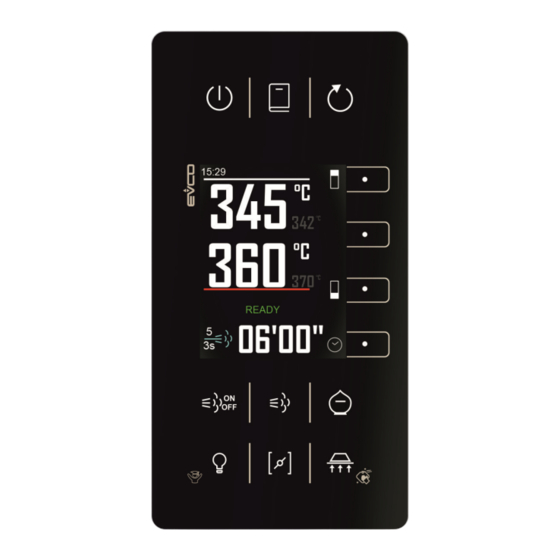
If the device is on and the operating logic has independent regulation of the top and floor tem-
perature (P2 = 1), the display will show:
If the top and floor setpoints have been reached, the status of the device will show "READY", if
not, it will show "PRE-HEATING".
If the device is switched off, the display will show the time. If the weekly programmed switch-
on function is activated, the display will also show the day and time of the next switch-on and
the programme that will start.
If the status of the device shows an alarm code, see the section ALARMS.
4.2
Starting up/interrupting the cooking cycle
To start up a cooking cycle:
-
make sure that the device is switched on
MIN... MAX.
-
make sure that the cooking timer is set
0 = J
1 = K
2 = Pt 100 2-wire
1.
0 = °C
1 = °F
0 = independent regulation of the
top and floor power
To interrupt the cooking cycle:
1 = independent regulation of the
top and floor temperature
1.
r1... r2
if P2 = 1, top setpoint
4.3
Setting the cooking timer
r4... r5
Make sure that the device is switched on.
1.
2.
3.
4.
5.
6.
4.4.1
Setting the chamber setpoint (if P2 = 0)
Make sure that the device is switched on.
1.
Touch the ON/STAND-BY key.
Touch the ON/STAND-BY key for 3 s.
Touch the START/STOP key: the cooking timer will start up and
the status of the device will show "COOKING". When the timer
stops, it will show "END".
Touch the START/STOP key for 1 s.
Touch the INTERACTIVE 4 key: the display will show the minutes
in yellow.
Touch the INTERACTIVE 1 key or the INTERACTIVE 2 key within
15 s to set the value.
Touch the INTERACTIVE 3 key: the display will show the seconds
in yellow.
Touch the INTERACTIVE 1 key or the INTERACTIVE 2 key within
15 s to set the value.
Touch the INTERACTIVE 3 key (or take no action for 15 s).
Touch the INTERACTIVE 4 key to exit the procedure beforehand
(any changes made will not be saved).
Touch the INTERACTIVE 2 key: the display will show the value in
yellow.
Advertisement
Table of Contents

Related Manuals for Evco EV8318


Summary of Contents for Evco EV8318
- Page 1 EVCO S.p.A. | EV8318 | Instr uction sheet ver. 2.0 | Code 1048318E203 | Page 1 of 4 | PT 47/18 EV8318 Controller for bread and pizza deck ovens ELECTRICAL CONNECTION USER INTERFACE AND MAIN FUNCTIONS N.B. - use cables of an adequate section for the current running through them...
- Page 2 EVCO S.p.A. | EV8318 | Instr uction sheet ver. 2.0 | Code 1048318E203 | Page 2 of 4 | PT 47/18 Touch the INTERACTIVE 1 key or the INTERACTIVE 2 key within Touch the INTERACTIVE 1 key or the INTERACTIVE 2 key within Touch the INTERACTIVE 4 key to exit the procedure (or take no 15 s to set the value within the limits r1 and r2 (default "0...
- Page 3 EVCO S.p.A. | EV8318 | Instr uction sheet ver. 2.0 | Code 1048318E203 | Page 3 of 4 | PT 47/18 SETTINGS maximum floor setpoint r4... 999 °C/°F multi-purpose input 2 function 0 = disabled 8.1 Setting configuration parameters (option...
- Page 4 EVCO S.p.A. | EV8318 | Instr uction sheet ver. 2.0 | Code 1048318E203 | Page 4 of 4 | PT 47/18 MODBUS baud rate 0 = 2,400 baud 1 = 4,800 baud 2 = 9,600 baud 3 = 19,200 baud...
Need help?
Do you have a question about the EV8318 and is the answer not in the manual?
Questions and answers
Si ta rris temperaturen me shumë se 300 °C