Table of Contents
Advertisement
Quick Links
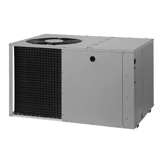
P5RF-ka / PPa2RFX-ka SERiES
inStallation inStRuctionS
SinglE PackagE aiR conditionER - 2 StagE, R410a
it is your responsibility to know this product better than your customer. this includes being
able to install the product according to strict safety guidelines and instructing the customer on
how to operate and maintain the equipment for the life of the product. Safety should always be
the deciding factor when installing this product and using common sense plays an important
role as well. Pay attention to all safety warnings and any other special notes highlighted in the
manual. improper installation of the furnace or failure to follow safety warnings could result in
serious injury, death, or property damage.
these instructions are primarily intended to assist qualified individuals experienced in the proper
installation of this appliance. Some local codes require licensed installation/service personnel
for this type of equipment. Please read all instructions carefully before starting the installation.
Return these instructions to the customer's package for future reference.
do not dEStRoY. PlEaSE REad caREFullY & kEEP in a SaFE PlacE FoR FutuRE REFEREncE.
iMPoRtant
attEntion inStallERS:
15 SEER
Advertisement
Table of Contents

Related Manuals for Nortek P5RF-KA Series


Summary of Contents for Nortek P5RF-KA Series
- Page 1 P5RF-ka / PPa2RFX-ka SERiES 15 SEER inStallation inStRuctionS SinglE PackagE aiR conditionER - 2 StagE, R410a iMPoRtant attEntion inStallERS: it is your responsibility to know this product better than your customer. this includes being able to install the product according to strict safety guidelines and instructing the customer on how to operate and maintain the equipment for the life of the product.
-
Page 2: Table Of Contents
tablE oF contEntS important Safety information ........3 Startup & adjustments ..........10 Pre - Start Checklist ..........10 general information ...........4 Start - Up Procedure ..........10 Before You Install this Unit .........4 Air Circulation ............10 Locating the Air Conditioner ........4 System Cooling ............10 Minimum Clearance Requirements ......4 System Heating ............10 Service Access Clearances ........4... -
Page 3: Important Safety Information
iMPoRtant SaFEtY inFoRMation caution: Please read all instructions before servicing this equipment. Pay attention to all safety warnings and any other special this unit uses R-410a refrigerant. do not use notes highlighted in the manual. Safety markings are any other refrigerant in this unit. use of another used frequently throughout this manual to designate a refrigerant will damage the unit. -
Page 4: General Information
gEnERal inFoRMation • The length of the supply and return ducts should be kept to a minimum with no sharp radius bends. This air conditioner is designed only for outdoor ground • Overhead obstructions, poorly ventilated areas, and level installations and can be readily connected to the areas subject to accumulation of debris should be high static duct system of a home. -
Page 5: Air Conditioner Installation
SinglE duct aPPlication MultiPlE duct aPPlication Figure 2. Single & Multiple duct applications aiR conditionER inStallation Return Duct 1. Assemble the collar by overlapping the two ends. unpacking the unit notE: One end of the collar is slotted and the opposite It is recommended that the unit be unpacked at the end has two small holes. -
Page 6: Locating & Installing The Return Air Assembly
ElEctRical connEctionS locating & installing the Supply damper(s) caution: WaRning: if installing this air conditioning system in to avoid risk of electrical shock, personal injury, conjunction with a furnace, a damper must be or death, disconnect all electrical power to the unit installed in the furnace base assembly to prevent before performing any maintenance or service. -
Page 7: Grounding
• Overcurrent protection must be provided at the branch grounding circuit distribution panel and sized as shown on the unit WaRning: rating label and according to applicable local codes. See the unit rating plate for minimum circuit ampacity the unit cabinet must have an uninterrupted or and maximum overcurrent protection limits. -
Page 8: Thermostat / Low Voltage Connections
Thermostat / Low Voltage Connections 2-stage Heat / Cool thermostat should be used with this • These units are designed to operate with a 24 VAC Class unit. The heat / cool thermostat prevents simultaneous II control circuit. The control circuit wiring must comply operation of the heating and cooling units and is equipped with the current provisions of the NEC (ANSI/NFPA with an ON-AUTO fan mode that allows the home owner... -
Page 9: Cooling Mode
Cooling Mode blower Speed 1. On a call for cooling, the thermostat closes, and For optimum system performance and comfort, it may applies 24VAC to the g & Y1 terminals of the control. be necessary to change the factory speed setting. See The compressor contactor closes and operates the Table 3 for factory settings. -
Page 10: Startup & Adjustments
StaRt uP & adJuStMEntS System Heating (Available only when Electric heat is supplied) Pre-Start checklist 1. Set the thermostat’s system mode to HEAT and the The following check list should be observed prior to fan mode to either AUTO (intermittent air) or to ON starting the unit. -
Page 11: Air Conditioner Maintenance
aiR conditionER MaintEnancE coMPonEnt FunctionS High Pressure Switch (HPS) WaRning: A high-pressure switch is factory-installed and located in the liquid line internal to the unit. The switch is designed to prevent electrical shock, personal injury, or to protect the system when very high pressures occur death, disconnect all electrical power to the unit during abnormal conditions. -
Page 12: Figures & Tables
FiguRES & tablES Top View 3” Rear Opening for View Opening for 14" Diameter 12" Diameter Return Duct Supply Duct 10.15 9.15 1.75” Ø Electric Heater 3.15 Power Supply 17.50 1” 1.13” Ø Power Supply .88” Ø Low Voltage Supply Control Blower Access Panel Access... -
Page 13: Refrigerant Charging Charts
REFRigERant cHaRging cHaRtS X24KA Charging Chart - Cooling Remove refrigerant when above curve Add refrigerant when below curve Liquid Temperature (F) Figure 8. charging chart for 2 ton units X36KA Charging Chart - Cooling Remove refrigerant when above curve Add refrigerant when below curve Liquid Temperature (F) Figure 9. - Page 14 REFRigERant cHaRging cHaRtS - continuEd X48KA Charging Chart - Cooling Remove refrigerant when above curve Add refrigerant when below curve Liquid Temperature (F) Figure 10. charging chart for 4 ton units X60KA Charging Chart - Cooling Remove refrigerant when above curve Add refrigerant when below curve Liquid Temperature (F) Figure 11.
-
Page 15: Wiring Diagrams
WiRing diagRaMS Figure 12. Wiring diagram for 2 & 3 ton units... - Page 16 Figure 13. Wiring diagram for 4 & 5 ton units...
-
Page 20: Installation / Performance Checklist
Failure to confirm proper charge and airflow may reduce energy efficiency and shorten equipment life. Specifications & illustrations subject to change without notice or incurring obligations (05/15). 709644a (Replaces 7096440) O’Fallon, MO, © Nortek Global HVAC LLC 2015. All Rights Reserved.
Need help?
Do you have a question about the P5RF-KA Series and is the answer not in the manual?
Questions and answers