Table of Contents
Advertisement
Quick Links
Advertisement
Table of Contents

Related Manuals for TLV SR-3


Summary of Contents for TLV SR-3
- Page 1 172-65207A-08 (SR-3/SR-8) 8 October 2020 Steam Condensing Heat Exchanger SR-3 / SR-8 Manufacturer 881 Nagasuna, Noguchi, Kakogawa, Hyogo, 675-8511, Japan Tel: [81]-(0)79-422-1122 Fax: [81]-(0)79-422-0112 Copyright © 2020 by TLV CO., LTD. All rights reserved...
-
Page 2: Table Of Contents
EXPRESS LIMITED WARRANTY ........ 21 Introduction Thank you for purchasing the TLV SR steam condensing heat exchanger. This product has been thoroughly inspected before being shipped from the factory. When the product is delivered, before doing anything else, check the specifications and external appearance to make sure nothing is out of the ordinary. -
Page 3: Safety Considerations
The three types of cautionary items above are very important for safety: be sure to observe all of them as they relate to installation, use, maintenance, and repair. Furthermore, TLV accepts no responsibility for any accidents or damage occurring as a result of failure to observe these precautions. - Page 4 If the water seal or inside of the tube freeze, the inside of the product may be pressurized which could cause problems on equipment or devices that are connected to the product. 172-65207MA-08 (SR-3/SR-8) 8 Oct 2020...
-
Page 5: Product Description
Product Description Intended Use The SR-3/SR-8 is an atmospheric indirect heat exchanger for recovering heat energy from waste or flash steam for applications where the steam cannot otherwise be utilized. By using this product for waste heat recovery or steam condensation, system energy efficiency, work environment, and plant scenery can be improved without increasing back pressure on steam-using equipment. -
Page 6: System Principle
System Principle Because the SR-3/SR-8 steam condensing heat exchanger does not have any valve parts on the Waste Steam Recovery side, it does not create any back-pressure on upstream equipment. For this reason, it can be directly connected to and used with feed water tanks and other vessels that do not meet pressure vessel regulations in most locations. -
Page 7: Specifications
Do not install valves or orifices at the exhaust outlet, since the SR is an atmospheric type heat exchanger. Maximum Operating Model Pressure Maximum Operating Temperature Heat Transfer Surface Area Maximum Steam Flow Rate Serial No. 172-65207MA-08 (SR-3/SR-8) 8 Oct 2020... -
Page 8: Configuration
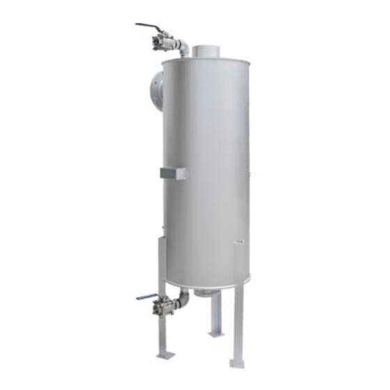
Configuration SR-3/SR-8 Appearance Internal Construction The figure above shows the SR-3. The internal configuration of the SR-8 differs slightly from the SR-3. * Depending on the specifications, the product may or may not feature an overflow outlet for the exhaust pipe. -
Page 9: Installation
We may not be able to perform technical support service in a location where work cannot be safely carried out. 172-65207MA-08 (SR-3/SR-8) 8 Oct 2020... - Page 10 3 o19 bolt hole Anchor bolts: Approx. 750 mm (2.5 ft) Total length: 220 mm (8 Approx. 2000 mm (6.6 ft) 3 pcs. Anchor bolts are selected with standard seismic intensity: 1, and horizontal seismic coefficient: 1. 172-65207MA-08 (SR-3/SR-8) 8 Oct 2020...
-
Page 11: Installation Example For Piping To/From The Sr Unit
Please carefully refer to the "Piping Installation" section described on the following pages for important points regarding piping arrangements. * Depending on the specifications, the product may or may not feature an overflow outlet for the exhaust pipe. 172-65207MA-08 (SR-3/SR-8) 8 Oct 2020... -
Page 12: Piping Installation 1: Waste Steam Inlet Piping
To handle steam without applying back pressure on steam-using equipment, it is recommended that the piping be of the same diameter as the SR steam inlet (SR-3: 80 mm (3 in), SR-8: 150 mm (6 in)). Suggested diameters for the steam inlet piping... -
Page 13: Piping Installation 2: Condensate Outlet Piping, Blowdown Piping And Overflow Piping For Exhaust Pipe
* Depending on the specifications, the product may or may not feature an overflow outlet for the exhaust pipe. Products without an overflow outlet should be fitted with an overflow line of nominal diameter 10 mm (3/8 in) or more. 172-65207MA-08 (SR-3/SR-8) 8 Oct 2020... -
Page 14: Piping Installation 3: Exhaust Piping
(66 ft to 98 ft) 30 m (98 ft) SR-3 50 mm (2 in) 80 mm (3 in) 100 mm (4 in) 150 mm (6 in) SR-8 80 mm (3 in) 100 mm (4 in) 150 mm (6 in) 172-65207MA-08 (SR-3/SR-8) 8 Oct 2020... - Page 15 C3 chamfering has been performed on the exhaust outlet. When welding is performed on the exhaust outlet, the connecting tube should be also chamfered and butt welded. Furthermore, when SUS304 is used for the SR, the piping thickness of the exhaust outlet will be “Sch40”. 172-65207MA-08 (SR-3/SR-8) 8 Oct 2020...
- Page 16 Screw holes on the exhaust port Two M5-sized screw holes are opened on either side of the exhaust port, intended for use with the standard duct connection. 172-65207MA-08 (SR-3/SR-8) 8 Oct 2020...
-
Page 17: Piping Installation 4: Water Inlet And Outlet Piping
9.8 ft/sec). Suggested diameters for the cold water inlet and hot water outlet piping are as follows: Water Flow (t/h) Pipe Diameter (mm) Water Flow (lb/h) 2000 4000 6000 8000 10000 12000 14000 16000 20000 Pipe Diameter (in) 172-65207MA-08 (SR-3/SR-8) 8 Oct 2020... -
Page 18: Operation
(if steam blow stops shortly then everything is normal) 172-65207MA-08 (SR-3/SR-8) 8 Oct 2020... - Page 19 (If the valve is closed rapidly, water hammer will occur, resulting in impacts to the SR and the surrounding piping.) 3. When the SR is to be shutdown for long periods of time, discharge all condensate by opening the blow valve (C) at the bottom of the body. 172-65207MA-08 (SR-3/SR-8) 8 Oct 2020...
-
Page 20: Inspection And Maintenance
1. Remove the plug from the inspection opening and check the condition inside the tank. 2. If the inspection reveals heavy grime, close the condensate outlet and the condensate blowdown outlet and perform chemical cleaning by pouring cleaning solution through the exhaust outlet of the SR. 172-65207MA-08 (SR-3/SR-8) 8 Oct 2020... -
Page 21: Troubleshooting
Little or no flow of water for heat Correct water flow equipment, or recovery steam cannot Accumulation of scale, etc. on Clean be discharged the heat transfer coils smoothly Correct the piping; see “Piping Incorrect piping at exhaust outlet Installation 3” 172-65207MA-08 (SR-3/SR-8) 8 Oct 2020... -
Page 22: Express Limited Warranty
Subject to the limitations set forth below, TLV Corporation, a North Carolina corporation (“TLV”) warrants that products which are sold by it, TLV CO., LTD., a Japanese corporation (“TLVJ”) or TLV International, Inc., a Japanese corporation (“TII”), which products (the “Products”) are designed and manufactured by TLVJ, conform to the specifications published by TLV for the corresponding part numbers (the “Specifications”) and are free from defective workmanship and... - Page 23 TRANSPORTATION COSTS ASSOCIATED WITH THE RETURN OR REPLACEMENT OF THE CLAIMED DEFECTIVE PRODUCT ARE SOLELY THE RESPONSIBILITY OF BUYER OR THE FIRST END USER. TLV RESERVES THE RIGHT TO INSPECT ON THE FIRST END USER’S SITE ANY PRODUCTS CLAIMED TO BE DEFECTIVE BEFORE ISSUING A RETURN MATERIAL AUTHORIZATION.
Need help?
Do you have a question about the SR-3 and is the answer not in the manual?
Questions and answers