Table of Contents
Advertisement
Quick Links
Operating Instructions
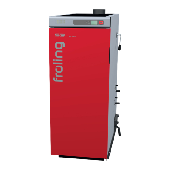
Firewood boiler S3 Turbo
Translation of the original German operating instructions for the operator
Read and follow the instructions and safety information!
Technical changes, typographical errors and omissions reserved!
B0610919_en | Edition 07/05/2019
Froling GesmbH | A-4710 Grieskirchen, Industriestraße 12 | www.froeling.com
Advertisement
Table of Contents
Troubleshooting

Related Manuals for Fröling S3 Turbo 15


Summary of Contents for Fröling S3 Turbo 15
- Page 1 Operating Instructions Firewood boiler S3 Turbo Translation of the original German operating instructions for the operator Read and follow the instructions and safety information! Technical changes, typographical errors and omissions reserved! B0610919_en | Edition 07/05/2019 Froling GesmbH | A-4710 Grieskirchen, Industriestraße 12 | www.froeling.com...
-
Page 2: Table Of Contents
Table of contents Table of contents General Operating principle S3 Turbo Product Overview Safety Hazard levels of warnings General safety information Permitted uses 2.3.1 The Clean Air Act 1993 and Smoke Control Areas 2.3.2 Permitted fuels Firewood 2.3.3 Fuels permitted under certain conditions Wood briquettes 2.3.4 Non-permitted fuels... - Page 3 Table of contents Heat up firewood manually Operate boiler using the button display Reloading firewood Switching off the boiler Switching off the power supply 4.10 Checking the ash level in the boiler 4.10.1 Removing ash 4.10.2 Clean the grating Servicing the system General information on servicing Required tools Maintenance work by the operator...
- Page 4 Table of contents Appendix Addresses 8.1.1 Address of manufacturer Customer service 8.1.2 Address of the installer Froling GesmbH | A-4710 Grieskirchen, Industriestraße 12 | www.froeling.com...
-
Page 5: General
General Operating principle 1 General Thank you for choosing a quality product from Froling. The product features a state-of- the-art design and conforms to all currently applicable standards and testing guidelines. Please read and observe the documentation provided and always keep it close to the system for reference. -
Page 6: S3 Turbo Product Overview
General S3 Turbo Product Overview 1.2 S3 Turbo Product Overview Insulated door Maintenance overview Fuel loading door Pre-heating chamber door Combustion chamber door with inspection glass S-Tronic Plus / S-Tronic Lambda controller Visual display showing operating statuses and parameters Status LED to display the operating status: - GREEN constant: BOILER ACTIVE (heating up/heating) - GREEN flashing (interval: 5 sec OFF, 1 sec ON): OFF - ORANGE flashing: WARNING... - Page 7 General S3 Turbo Product Overview Underneath the back insulating cover (9): Lever of the heat exchanger cleaner (WOS system) For S-Tronic Plus: Manual adjusters for primary and secondary air For S-Tronic Lambda: Servo-motors for primary and secondary air (Air duct system set by qualified technician during initial start-up) Cleaning door Back insulating cover Heat exchanger cover: Maintenance opening for cleaning the WOS system and heat...
-
Page 8: Safety
Safety Hazard levels of warnings 2 Safety 2.1 Hazard levels of warnings This documentation uses warnings with the following hazard levels to indicate direct hazards and important safety instructions: DANGER The dangerous situation is imminent and if measures are not observed it will lead to serious injury or death. -
Page 9: General Safety Information
Safety General safety information 2.2 General safety information DANGER If the device is used incorrectly: Incorrect use of the system can cause severe injury and damage. When operating the system: ❒ Observe the instructions and information in the manuals. ❒ Observe the details on procedures for operation, maintenance and cleaning, as well as troubleshooting in the individual manuals. -
Page 10: Permitted Uses
Safety Permitted uses 2.3 Permitted uses The Froling Firewood boiler S3 Turbo is designed solely for heating domestic water. Only the fuels specified in the "Permitted fuels" section may be used. ⇨ See "Permitted fuels" [page 11] The unit should only be operated when it is in full working order. It must be operated in accordance with the instructions, observing safety precautions, and you should ensure you are aware of the potential hazards. -
Page 11: Permitted Fuels
Safety Permitted uses 2.3.2 Permitted fuels Firewood Firewood up to max. 55 cm long. Water content Water content (w) greater than 15% (equivalent to wood moisture u > 17%) Water content (w) less than 25% (equivalent to wood moisture u < 33%) Note on standards Fuel as per EN ISO 17225 –... - Page 12 Safety Permitted uses Note on standards Fuel as per EN ISO 17225 - Part 3: wood briquettes class B / D100 L500 Form 1 - 3 Additional for Germany: Fuel class 5a (§3 of the First Federal Emissions Protection Ordinance (BImSchV) - applicable version) Notes on ▪...
-
Page 13: Non-Permitted Fuels
Safety Permitted uses 2.3.4 Non-permitted fuels The use of fuels not defined in the "Permitted fuels" section, and particularly the burning of refuse, is not permitted. CAUTION In case of use of non-permitted fuels: Burning non-permitted fuels increases the cleaning requirements and leads to a build-up of aggressive sedimentation and condensation, which can damage the boiler and also invalidates the guarantee. -
Page 14: Safety Devices
Safety Safety devices 2.6 Safety devices Underneath the back insulating cover: (protection against overheating) HIGH-LIMIT THERMOSTAT (STL) The STL switches off the combustion system when the boiler reaches 105°C. The pumps continue to run. Once the temperature falls below approx. 75°C, the STL can be reset mechanically. -
Page 15: Residual Risks
Safety Residual risks 2.7 Residual risks WARNING When the main switch is switched off in heating mode: The boiler is not controlled. Any resulting boiler malfunctions can cause serious injury and damage. Take the following precautions: ❒ Allow the fire to burn out completely and let the boiler cool ➥... -
Page 16: Emergency Procedure
Safety Emergency procedure WARNING If non-permitted fuel types are used: Non-standard fuels can cause serious faults in combustion (e.g. spontaneous combustion of carbonisation gases / flash fires) which can lead to serious accidents! Take the following precautions: ❒ Only use fuels specified in the "Permitted fuels" section of these operating instructions. -
Page 17: Power Failure / Induced Draught Fan Failure
Safety Emergency procedure 2.8.3 Power failure / induced draught fan failure A power failure, among others, can be identified based on the following points: ▪ Display remains dark despite touching it ▪ LED status does not flash / light up ▪... -
Page 18: Notes For Operating A Heating System
Notes for operating a heating system Installation and approval of the heating system 3 Notes for operating a heating system Carrying out modifications to the system and changing or disabling safety equipment is prohibited. Always comply with all fire, building and electrical regulations when installing or operating the system, in addition to following the operating instructions and mandatory regulations that apply in the country in which the tank is operated. -
Page 19: Requirements For Central Heating Water
Notes for operating a heating system General information for installation room (boiler room) ▪ The system must be protected against the chewing or nesting of animals (e.g. rodents etc.). Ventilation of the boiler room Ventilation air for the boiler room should be taken from and expelled directly outside, and the openings and air ducts should be designed to prevent weather conditions (foliage, snowdrifts, etc.) from obstructing the air flow. -
Page 20: Notes For Using Pressure Maintenance Systems
Notes for operating a heating system Notes for using pressure maintenance systems Permitted water hardness for the fill and make-up water in accordance with VDI 2035: Overall heat Total hardness at Total hardness at Total hardness at output <20 l/kW minimum >20 <50 l/kW minimum >50 l/kW minimum individual heat output... -
Page 21: Return Lift
Notes for operating a heating system Return lift Pump-controlled pressure maintenance A pump-controlled pressure maintenance unit essentially consists of a pressure- maintenance pump, relief valve and an unpressurised receiving tank. The valve releases hot water into the receiving tank if the pressure is too high. If the pressure drops below a preset value, the pump draws water from the receiving tank and feeds it back into the heating system. -
Page 22: Operating The System
Operating the system Assembly and initial startup 4 Operating the system 4.1 Assembly and initial startup Assembly, installation and initial startup of the boiler must only be carried out by qualified staff, and these procedures are described in the accompanying assembly instructions. -
Page 23: Switching On The Power Supply
Operating the system Switching on the power supply 4.2 Switching on the power supply ❒ Turn on the main switch ➥ There is voltage at all of the boiler's components ➥ When the control has completed the system start, the boiler is ready for operation 4.3 Switching on the boiler ❒... -
Page 24: Determining The Right Amount Of Fuel
Operating the system Before heating up the boiler 4.4.3 Determining the right amount of fuel The amount of fuel added should allow the storage tank to be constantly heated to the max. storage tank temperature (= boiler target temperature). Please note that the amount to reload also depends on the type of fuel. -
Page 25: Fuel Table
Operating the system Before heating up the boiler 4.4.4 Fuel table The table below shows a selection of wood types with the corresponding energy content depending on the water content: Wood type Energy content with water content [kWh/kg] w = 15% w = 20% w = 25% Spruce... -
Page 26: Heat Up Firewood Manually
Operating the system Heat up firewood manually 4.5 Heat up firewood manually ❒ Open the insulated door and the fuel loading door ➥ It is recommended that you do not remove the ash in the combustion chamber during each heating-up process, but rather only when the middle row of holes is no longer visible. -
Page 27: Operate Boiler Using The Button Display
Operating the system Operate boiler using the button display ❒ Fill the fuel loading chamber according to the expected consumption and close the fuel loading chamber door ⇨ See "Determining the right amount of fuel" [page 24] ❒ Open the pre-heating door, insert scrunched up paper and light If the underpressure from the induced draught fan is too strong for the firing material to be ignited: ❒... -
Page 28: Reloading Firewood
Operating the system Reloading firewood 4.7 Reloading firewood WARNING Touching hot surfaces behind the insulated door can cause burns! By the nature of its operation, the surfaces and operating elements in the area behind the insulated door get hot! When working with firewood, there is also a risk of injury from splinters. -
Page 29: Switching Off The Boiler
Operating the system Switching off the boiler 4.8 Switching off the boiler ❒ Press the standby key (key control panel) ➥ The boiler follows the shutdown program and switches to "Off“ status ➥ The combustion unit is switched off, the chamber discharge unit and the entire hydraulic system remain active 4.9 Switching off the power supply WARNING... -
Page 30: Checking The Ash Level In The Boiler
Operating the system Checking the ash level in the boiler 4.10 Checking the ash level in the boiler NOTICE Cracks in the combustion chamber may occur during operation. If the fireclay elements and the surrounding seals remain in their original position, existing cracks do not represent a malfunction! 4.10.1 Removing ash Recommendation: Do not remove the ash in the combustion chamber each time you... -
Page 31: Clean The Grating
Operating the system Checking the ash level in the boiler ❒ Clean the passage to the left and right of the combustion chamber with small brush and remove ash ❒ Empty the ash into the container provided ➥ Use a fire-proof container with cover 4.10.2 Clean the grating ❒... -
Page 32: Servicing The System
Servicing the system General information on servicing 5 Servicing the system 5.1 General information on servicing DANGER When working on electrical components: Risk of electrocution! When work is carried out on electrical components: ❒ Always have work carried out by a qualified electrician ❒... -
Page 33: Required Tools
Servicing the system Required tools WARNING Incorrect inspection and cleaning: Incorrect or insufficient inspection and cleaning of the boiler can cause serious faults in combustion (e.g. spontaneous combustion of carbonisation gases / flash fires) and this can lead to serious accidents and damage! Take the following precautions: ❒... -
Page 34: Maintenance Work By The Operator
Servicing the system Maintenance work by the operator 5.3 Maintenance work by the operator ❒ Regular cleaning of the boiler extends its life and is a basic requirement for smooth running. ❒ Recommendation: use an ash vacuum for cleaning. 5.3.1 Inspection Checking the system pressure ❒... -
Page 35: Periodic Inspection And Cleaning
Servicing the system Maintenance work by the operator 5.3.2 Periodic inspection and cleaning The boiler must be inspected and cleaned at appropriate intervals depending on the operating hours and fuel quality. Inspection and cleaning must be repeated after not more than 1500 operating hours or at least once a year. -
Page 36: Checking The Primary Air Openings
Servicing the system Maintenance work by the operator Checking the primary air openings ❒ Open the insulated door and the fuel loading chamber door ❒ Hang out and remove the combustion chamber guards ❒ Check the primary air openings for unobstructed air flow ❒... -
Page 37: Clean The Heat Exchanger Pipes
Servicing the system Maintenance work by the operator Clean the heat exchanger pipes ❒ Lift off the back insulating cover and remove the heat exchanger cover ➥ Use spanner (A) provided ❒ Remove the pipe locking pin (B) and take out the WOS lever ❒... -
Page 38: Cleaning The Flue Gas Pipe
Servicing the system Maintenance work by the operator S3 Turbo 20-30 S3 Turbo 40-45 ❒ Before fitting in the heat exchanger pipes, check that the WOS springs are correctly hooked into the linking plate ➥ The protruding, canted sheet-metal strips must face upwards and the turbulators must be hooked in as shown ❒... -
Page 39: Checking The Draught Controller Flap
Servicing the system Maintenance work by the operator Checking the draught controller flap ❒ Check that the draught controller flap moves freely Checking the seal on the doors Checking the tightness is shown below using the example of the fuel loading door and is carried out in the same way for the other boiler doors. -
Page 40: Cleaning The Induced Draught Fan
Servicing the system Maintenance work by the operator Cleaning the induced draught fan Check the induced draught fan for dirt and deposits and clean if necessary NOTICE! Deposits on the running wheel can cause an imbalance in the ID fan, which can result in noise or, in the worst case, bearing damage. -
Page 41: Maintenance Work By Technicians
Servicing the system Maintenance work by technicians 5.4 Maintenance work by technicians CAUTION If maintenance work is carried out by untrained personnel: Risk of personal injury and damage to property! The following applies for maintenance: ❒ Observe the instructions and information in the manuals ❒... -
Page 42: Cleaning The Lambda Probe
Servicing the system Maintenance work by technicians 5.4.1 Cleaning the Lambda probe NOTICE! Lambda probe only installed on S3 Turbo with S-Tronic Lambda! ❒ Carefully remove Lambda probe with plastic bushing ➥ Pay attention to the cables of the Lambda probe! ❒... -
Page 43: Emissions Measurement By Chimney Sweep Or Regulatory Body
Servicing the system Emissions measurement by chimney sweep or regulatory body 5.5 Emissions measurement by chimney sweep or regulatory body Various legal regulations stipulate that heating systems must be inspected periodically. In Germany this is regulated by the First Federal Emissions Protection Ordinance (BimSchV) in the last amended version, and in Austria by various state laws. -
Page 44: Performing The Emissions Measurement
Servicing the system Emissions measurement by chimney sweep or regulatory body 5.5.2 Performing the emissions measurement Create the measurement conditions and perform the measurement ❒ Fill the boiler approx. 1/4 full with small pieces of split wood in accordance with the operating instructions and heat up ➥... -
Page 45: Replacement Parts
Servicing the system Replacement parts 5.6 Replacement parts With Froling original replacement parts in your boiler, you are using parts that match perfectly. As the parts fit together so well, installation times are shortened and a long service life is maintained. NOTICE Installing non-original parts will invalidate the guarantee. -
Page 46: Troubleshooting
Troubleshooting General fault with power supply 6 Troubleshooting 6.1 General fault with power supply Error characteristics Cause of error Elimination of error Nothing is shown on the General power failure display Main switch is turned off Turn on the main switch No power to the controller FI circuit breaker or line Switch on the FI circuit... -
Page 47: Faults With Fault Message - Key Control
Troubleshooting Faults with fault message - Key control 6.3 Faults with fault message - Key control 6.3.1 Troubleshooting The term "fault" is a collective term for warnings, errors and alarms. The boiler reacts differently to the three types of message: WARNING In case of warnings the status LED flashes orange and the boiler initially continues controlled operation. -
Page 48: Acknowledging A Fault Message
Troubleshooting Acknowledging a fault message 6.4 Acknowledging a fault message Trace and remove the fault and then: ❒ Press the Enter key ➥ Status LED constant or flashing green light (depending on operating status) - Green constant: Heating up/Heating - Green flashing: Off Froling GesmbH | A-4710 Grieskirchen, Industriestraße 12 | www.froeling.com... -
Page 49: Notes
Notes 7 Notes Operating Instructions S3 Turbo | B0610919_en... - Page 50 Notes Froling GesmbH | A-4710 Grieskirchen, Industriestraße 12 | www.froeling.com...
- Page 51 Notes Operating Instructions S3 Turbo | B0610919_en...
- Page 52 Appendix Addresses 8 Appendix 8.1 Addresses 8.1.1 Address of manufacturer FRÖLING Heizkessel- und Behälterbau GesmbH Industriestraße 12 A-4710 Grieskirchen AUSTRIA TEL 0043 (0)7248 606 0 FAX 0043 (0)7248 606 600 EMAIL info@froeling.com INTERNET www.froeling.com Customer service Austria 0043 (0)7248 606 7000 Germany 0049 (0)89 927 926 400 Worldwide...
Need help?
Do you have a question about the S3 Turbo 15 and is the answer not in the manual?
Questions and answers