Sign In
Upload
Download
Table of Contents
Contents
Add to my manuals
Delete from my manuals
Share
URL of this page:
HTML Link:
Bookmark this page
Add
Manual will be automatically added to "My Manuals"
Print this page
×
Bookmark added
×
Added to my manuals
Manuals
Brands
Fröling Manuals
Boiler
S4 Turbo 15
Operating instructions manual
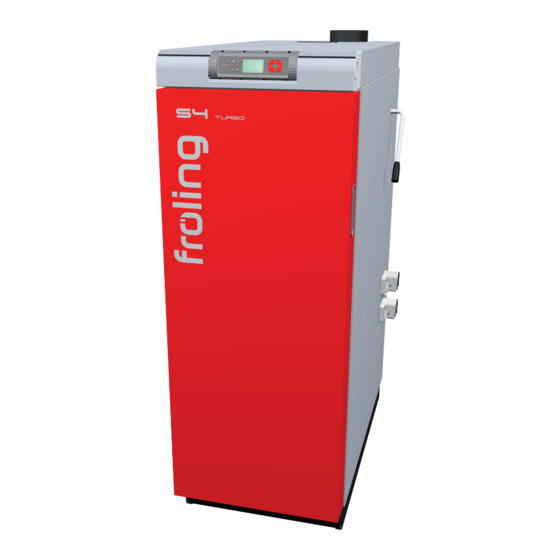
Fröling S4 Turbo 15 Operating Instructions Manual
Firewood boiler
Hide thumbs
1
Table Of Contents
2
3
4
5
6
7
8
9
10
11
12
13
14
15
16
17
18
19
20
21
22
23
24
25
26
27
28
29
30
31
32
33
34
35
36
37
38
39
40
41
42
43
44
45
46
47
48
49
50
51
52
53
54
55
56
57
58
59
60
61
62
63
64
65
66
67
68
69
70
71
72
73
74
75
76
77
78
79
80
page
of
80
Go
/
80
Contents
Table of Contents
Troubleshooting
Bookmarks
Table of Contents
Table of Contents
General
Operating Principle
S4 Turbo Product Overview
Safety
Hazard Levels of Warnings
Pictograms Used
General Safety Information
Permitted Uses
Permitted Fuels
Fuels Permitted under Certain Conditions
Non-Permitted Fuels
Qualification of Operating Staff
Protective Equipment for Operating Staff
Safety Devices
Residual Risks
Emergency Procedure
Overheating of the System
Smell of Flue Gas
Power Failure / Induced Draught Fan Failure
Fire in the System
Notes for Operating a Heating System
Installation and Approval
Installation Site
Combustion Air
Combustion Air Supply at the Installation Room
Simultaneous Operation with Other Air-Drawing Systems
Domestic Hot Water
Pressure Maintenance Systems
Return Lift
Combination with Storage Tank
Chimney Connection/Chimney System
Operating the System
Assembly and Initial Startup
Switching on the Power Supply
Before Heating up the Boiler
Clean the Heat Exchanger Pipes
Check the Ignition Pipe (Only with Automatic Ignition)
Reloading Intervals When Operating with Storage Tank
Reload Quantity Calculation
Determining the Right Amount of Fuel
Reloading Intervals When Operating Without Storage Tank or if the Storage Tank Is too Small
Heat up Firewood Manually
Heat up the Firewood with Automatic Ignition
Operate the Boiler Using the Touch Display
Overview of the Touch Display
Select Information Displays
Change Boiler Mode
Change Date and Time
Change Desired DHW Tank Temperature
One-Time Extra Loading of an Individual DHW Tank
One-Time Extra Loading of All Existing DHW Tanks
Set the Heating Curve of a Heating Circuit
Change Room Temperature (Heating Circuit Without Room Temperature Sensor)
Change Room Temperature (Heating Circuit with Room Temperature Sensor)
Switch Heating Circuit Mode
Lock Display/Switch User Level
Change the Name of the Components
Configure the Holiday Program
Activate Automatic Ignition
Reloading Firewood
Switching off the Power Supply
Checking the Ash Level in the Boiler
Emptying Ash
Cleaning the Grating
Servicing the System
General Information on Servicing
Required Tools
Maintenance Work by the Operator
Inspection
Periodic Inspection and Cleaning
Servicing the Condensing Boiler Heat Exchanger (Optional)
Inspecting the Heat Exchanger
Checking the Condensation Drain
Maintenance Work by Technicians
Cleaning the Lambda Probe
Emissions Measurement by Chimney Sweep or Regulatory Body
General Information on Measurement
Create the Measurement Conditions and Perform the Measurement
Replacement Parts
Disposal Information
Disposal of the Ash
Disposal of System Components
Troubleshooting
General Fault with Power Supply
Behaviour of System after a Power Failure
Extra Cleaning of Flue Gas Paths
Excessive Temperature
Faults with Fault Message
Procedure for Fault Messages
Advertisement
Quick Links
Download this manual
Operating instructions
Firewood boiler S4 Turbo
Translation of original German version of operating instructions for operators.
Read and follow all instructions and safety instructions.
All errors and omissions excepted.
B1510622_en | Edition 02/11/2022
Table of
Contents
Previous
Page
Next
Page
1
2
3
4
5
Advertisement
Table of Contents
Need help?
Do you have a question about the S4 Turbo 15 and is the answer not in the manual?
Ask a question
Questions and answers
Related Manuals for Fröling S4 Turbo 15
Boiler Fröling S4 Turbo 22 Installation Instructions Manual
Firewood boiler (92 pages)
Boiler Fröling S4 Turbo 20 Operating Instructions Manual
Firewood boiler (80 pages)
Boiler Fröling S4 Turbo (F) Operating Instructions Manual
Firewood boiler (76 pages)
Boiler Fröling Lambdatronic S 3200 Service Handbook
(96 pages)
Boiler Fröling S4 Turbo F 28 Installation Instructions Manual
Firewood boiler (92 pages)
Boiler Fröling S4 Turbo F 34 Installation Instructions Manual
Firewood boiler (92 pages)
Boiler Fröling S4 Turbo F 40 Installation Instructions Manual
Firewood boiler (92 pages)
Boiler Fröling Lambdatronic SP 3200 Service Manual
(129 pages)
Boiler Fröling Lambdatronic SP 3200 Service Handbook
(120 pages)
Boiler Fröling S3 Turbo Installation Instructions Manual
Firewood boiler (67 pages)
Boiler Fröling FHG Turbo Assembly Instructions Manual
Combustion chamber (11 pages)
Boiler Fröling SP Dual compact 15 Operating Instructions Manual
Dual fuel boiler (80 pages)
Boiler Fröling Lambdatronic S 3100 Instructions Manual
(36 pages)
Boiler Fröling S-Tronic Lambda Service Handbook
(100 pages)
Boiler Fröling S1 Turbo 15 Installation Instructions Manual
Firewood boiler (64 pages)
Boiler Fröling S1 Turbo F 20 Installation Instructions Manual
Firewood boiler (64 pages)
This manual is also suitable for:
S4 turbo 20
S4 turbo 18
S4 turbo 28
S4 turbo 36
S4 turbo 45
Table of Contents
Print
Rename the bookmark
Delete bookmark?
Delete from my manuals?
Login
Sign In
OR
Sign in with Facebook
Sign in with Google
Upload manual
Upload from disk
Upload from URL


Need help?
Do you have a question about the S4 Turbo 15 and is the answer not in the manual?
Questions and answers