Sign In
Upload
Download
Add to my manuals
Delete from my manuals
Share
URL of this page:
HTML Link:
Bookmark this page
Add
Manual will be automatically added to "My Manuals"
Print this page
×
Bookmark added
×
Added to my manuals
Manuals
Brands
Sorotec Manuals
Power Tool
ALU 0605
Assembly instructions manual
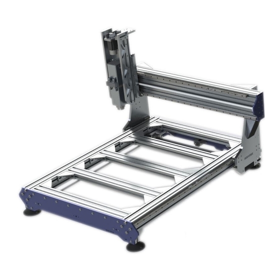
Sorotec ALU 0605 Assembly Instructions Manual
Cnc portal milling machine kit
Hide thumbs
1
2
3
4
5
6
7
8
9
10
11
12
13
14
15
16
17
18
19
20
21
22
23
24
25
26
27
28
29
30
31
32
33
34
page
of
34
Go
/
34
Bookmarks
Advertisement
Quick Links
Download this manual
CNC portal milling machine kit
SOROTEC GmbH
Withig 12
77836 Rheinmünster
Assembly instructions
Alu-Line
Tel.: +49 (0) 7227-994255-0
Fax: +49 (0) 7227-994255-9
E-Mail: sorotec@sorotec.de
Web: www.sorotec.de
MPF.ALxxxx.01.B
Version 2.0.0
Previous
Page
Next
Page
1
2
3
4
5
Advertisement
Need help?
Do you have a question about the ALU 0605 and is the answer not in the manual?
Ask a question
Questions and answers
Related Manuals for Sorotec ALU 0605
Power Tool Sorotec ALU 1107 Assembly Instructions Manual
Cnc portal milling machine kit (34 pages)
Power Tool Sorotec ALU 1110 Assembly Instructions Manual
Cnc portal milling machine kit (34 pages)
Power Tool Sorotec 0605 Assembly Instructions Manual
Cnc portal milling machine kit basic-line (29 pages)
Power Tool Sorotec COMPACT 0403 Assembly Instructions Manual
Cnc portal milling machine kit compact-line (23 pages)
Power Tool Sorotec Hobby Line MPF.HL1.4530 Operation Manual
(16 pages)
This manual is also suitable for:
Alu 0607
Alu 0610
Alu 1105
Alu 1107
Alu 1110
Alu 1105 heavy
...
Show all
Alu 1107 heavy
Alu 1505 heavy
Alu 1507 heavy
Alu 1510 heavy
Alu 2007 heavy
Alu 2010 heavy
Alu 2013 heavy
Alu 1105 heavy gantry
Alu 1107 heavy gantry
Alu 1507 heavy gantry
Alu 1510 heavy gantry
Alu 2010 heavy gantry
Alu-line 1513 heavy
Print
Rename the bookmark
Delete bookmark?
Delete from my manuals?
Login
Sign In
OR
Sign in with Facebook
Sign in with Google
Upload manual
Upload from disk
Upload from URL


Need help?
Do you have a question about the ALU 0605 and is the answer not in the manual?
Questions and answers