
Related Manuals for Sorotec 0605


Summary of Contents for Sorotec 0605
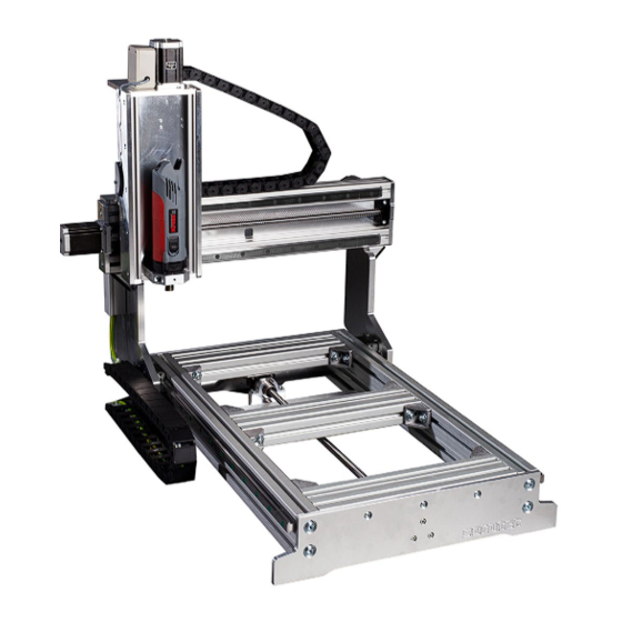
- Page 1 Assembly instructions CNC portal milling machine kit Basic-Line MPF.BLxxxx.01.B SOROTEC GmbH Tel.: +49 (0) 7227-994255-0 Withig 12 Fax: +49 (0) 7227-994255-9 77836 Rheinmünster E-Mail: sorotec@sorotec.de Version 2.3.3 Web: www.sorotec.de...
-
Page 2: Technical Specifications
© 2023 Sorotec GmbH Reproduction, duplication or translation, also in extracts, without the written approval of Sorotec GmbH is not permitted. All rights under the Copyright Act remain the Sorotec GmbH expressly reserved. Technical changes reserved. Made in Germany. -
Page 3: Required Tools
M5 to M8 is recommended. By observing the prescribed tightening torque also prevents unwanted Sorotec GmbH assumes no liability for damage to loosening during later operation of the machine. property or personal injury occurring during assem-... - Page 4 Because the head of the countersunk screw disappears into the material, the head height here is part of the length. So the length is measured over everything. But really: Only with the countersunk screw! SOROTEC GmbH Tel.: +49 (0) 7227-994255-0 Withig 12 Fax: +49 (0) 7227-994255-9 77836 Rheinmünster...
-
Page 5: Scope Of Delivery
Claw clutch CL.ZAN.LL16.H MZK.080.100.V25 Drive Z: fixed bearing CL.ZAN.FL16.H Ball screw Carriage ZAN.NTS.KGS1605.0270.M ZFW.NTS.HGH20CA Recirc. ball nut readily mounted on ball screw Stiffeners Z: Linear rail X left / right see page 6 BL.FT.022.01 www.sorotec.de Page 3/26 V 2.3.3... - Page 6 Angle 20 x 20 Profile 10 45 x 90 light BL.PR.W.052020 see page 6 including cover Profile 10 45 x 90 Angle 40 x 40 heavy (819 mm lg.) AL.PR.WS.084040 including cover see page 6 www.sorotec.de Page 4/26 V 2.3.3...
- Page 7 3D.PR.NS.05M5S MED.SUS.V.03 MED.SUS.V.08 Hammer nut Slot 8 M5 AL.PR.HM.08M5.017 Slot 8 M6 AL.PR.HM.08M6.017 Dowel pin hard DIN 6325 Slot 10 M5 AL.PR.HM.10M5.030 5 x 18 mm Slot 10 M6 AL.PR.HM.10M6.030 AL.ZS.05.18 Slot 10 M8 AL.PR.HM.10M8.030 www.sorotec.de Page 5/26 V 2.3.3...
- Page 8 Assembly instructions Basic-Line kit Order numbers of size-dependent parts Maschine Bezeichnung BL 0605 BL 0607 BL 1005 BL 1007 Ball screw X ZAN.NTS.KGS1610.0800.M ZAN.NTS.KGS1610.0800.M ZAN.NTS.KGS1610.1200.M ZAN.NTS.KGS1610.1200.M Ball screw Y ZAN.NTS.KGS1610.0650.M ZAN.NTS.KGS1610.0850.M ZAN.NTS.KGS1610.0650.M ZAN.NTS.KGS1610.0850.M Linear rail X BL.ZFS.HGR20R.0817.BL BL.ZFS.HGR20R.0817.BL BL.ZFS.HGR20R.1217.BL BL.ZFS.HGR20R.1217.BL Linear rail Y BL.ZFS.HGR20R.0622.BL...
- Page 9 Fixed bearing (above) and floating bearing in a Sorotec Alu-Line Compromise: tight but not clamped In practice, a workable compromise is usually reached by sliding the floating bearing tightly onto the end of the shaft, but without using much force.
-
Page 10: Preparatory Work
(all drives): Equip all ball nuts with 90° angled grease nipples (see picture 2). Do not fully tighten the grease nipples to be able to align them later. Fig 2: Bore and thread for grease nipples www.sorotec.de Page 7/26 V 2.3.3... - Page 11 • Place the floating bearing on the ball screw. Install floating bearing Y drive • Place the floating bearing unit on the ball screw and attach the circlip to the end of the ball screw. Fig 6: Floating bearing assembly www.sorotec.de Page 8/26 V 2.3.3...
- Page 12 Assembly instructions Basic-Line kit Assembly X axis and base frame Note: The following illustrations show the Basic-Line 0605 kit. The Basic-Line 1005 is installed analogously. Fig. 7: Completely assembled base frame • Screw the linear guide to the profile The lower edge of the linear guide must lie along the milled stop edge of the profile over its entire length (see Figure 8).
- Page 13 Fig. 12: Lubricating nipples on the carriage point outwards Note: The illustration shows the assembly with the Per- formance Kit, i.e. with two carriages per side on the guide of the X axis. www.sorotec.de Page 10/26 V 2.3.3...
- Page 14 ; Tighten screws slightly. Note: The fastening screws of the bearing units are not tightened until aligning. For the following reference switch assembly, if ne- cessary, observe the additional instructions for as- sembly „Electrical installation kit“. www.sorotec.de Page 11/26 V 2.3.3...
- Page 15 Fig. 15: Assembly of the X reference switch Assembly of Y-axis / portal Note: The following illustration shows the assembly without a performance kit, i.e. with one carriage per side on the X axis. Fig. 16: Fully assembled portal with Y axis www.sorotec.de Page 12/26 V 2.3.3...
- Page 16 • Place the portal beam on the two portal cheeks as shown and screw all angles to the portal cheeks with flat-head screws and hammer nuts ; Tighten screws slightly. Fig. 19: Connection of portal beams and cheeks www.sorotec.de Page 13/26 V 2.3.3...
- Page 17 • Check whether the portal can be easily moved over the entire travel path over the base frame after all screws have been tightened. Fig. 22: Setting the parallelism of the basic frame www.sorotec.de Page 14/26 V 2.3.3...
- Page 18 Schraubenanzugsdrehmo-ment: 6 Nm Tighten the fastening screws of the flange plate . Tightening torque: 6 Nm • Drive the dowel pins into the Y slide flush to the back. Fig. 26: Dowel pins in sledge www.sorotec.de Page 15/26 V 2.3.3...
- Page 19 ; Tighten screws slightly Fig. 28: Assembly of flange bracket and Y-slide • Move the slide Y to the fixed bearing by turning the ball screw until the fixing screws of the fixed bearing are just accessible. www.sorotec.de Page 16/26 V 2.3.3...
- Page 20 • Place the shim between the reference switch and switch carrier Y and screw the reference switch to the switch carrier Y using cylinder head screws and a washer Fig. 32: Installation of Y reference switch www.sorotec.de Page 17/26 V 2.3.3...
- Page 21 After aligning the Z axis, the side braces Z are finally installed. When equipped with a performance kit, the stronger parts of the kit are used instead of the simp- le reinforcements. Fig. 34: Screwing the Z-axis onto the guide plate www.sorotec.de Page 18/26 V 2.3.3...
- Page 22 - Grease nipple on the carriage points up and left • Push the linear rail Z into the carriage, press the carriage against the dowel pins and tighten the fastening screws of the carriage. Tightening torque: 6 Nm www.sorotec.de Page 19/26 V 2.3.3...
- Page 23 • Move the base plate Z to the fixed bearing as far as possible by turning the ball screw • Carefully tighten the screws of the flange bracket Z • Tighten the screws of the fixed bearing Tightening torque: 10 Nm www.sorotec.de Page 20/26 V 2.3.3...
- Page 24 Z and tighten screws • Align stop plate Z and motor flange Z flush and tighten screws • Mount the pre-assembled Z-axis on the slide Y using socket head screws ; Tighten screws slightly. www.sorotec.de Page 21/26 V 2.3.3...
- Page 25 Z and screw on a sliding block on the inside. • Push the hammer nuts of the bracings Z into the profiles from above. • Align bracings Z flush and tighten screws. www.sorotec.de Page 22/26 V 2.3.3...
- Page 26 In this case, lubricate the plastic buffer with a • Fix the stepper motor with the claw coupling little Vaseline. Under no circumstances use normal locking screw. grease or lubricating oil! Ordinary lubricants attack the plastic and can destroy it. www.sorotec.de Page 23/26 V 2.3.3...
-
Page 27: Maintenance
As a grease gun, we recommend the „HIWIN twelve months. To do this, proceed as follows: grease gun“ set from the Sorotec online shop (item no. SM.00014). All lubrication points Common multi-purpose grease is sufficient to After greasing, remove excess grease with a rag. - Page 28 Y-spindle nut is now easily accessible through the opening in the middle of the portal beam. • Lubricate the Y-spindle nut as shown in Figure Fig. 47: Lubricating Y-axis spindle nut www.sorotec.de Page 25/26 V 2.3.3...
- Page 29 Spindle nut Z axis The grease nipple on the spindle nut of the Z axis is easily accessible from behind and above. • Lubricate the Z-spindle nut as shown in Figure Fig. 49: Lubricating Z-axis spindle nut www.sorotec.de Page 26/26 V 2.3.3...
Need help?
Do you have a question about the 0605 and is the answer not in the manual?
Questions and answers