
Related Manuals for Sorotec ALU 1107


Summarization of Contents
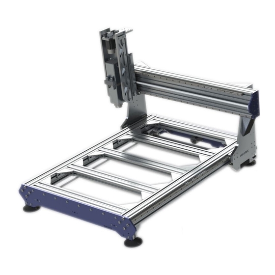
Introduction to Alu-Line CNC Milling Machine
General Information on Assembly
Emphasizes careful assembly and alignment for accuracy, and checking components for defects before use.
Optional Accessories Overview
Lists available accessories like milling spindles, base frames, and control software found in the Sorotec shop.
Infosheet on Measuring Screws
Screw Dimensions Explained
Explains screw sizing format (diameter x length) and units for metric and wood screws.
Measuring Screw Diameter
Details measuring screw diameter with a vernier caliper on the outside of the thread.
Measuring Screw Length
Describes measuring screw length including parts that disappear into material, using depth gauge.
Countersunk Screw Length Exception
Notes that head height is part of the length for countersunk screws, measured over everything.
Scope of Delivery for Alu-Line Kit
Included Parts List
Lists all included parts with illustrations, descriptions, and quantities for the Alu-Line kit.
Order Numbers for Size-Dependent Parts
Part Numbering System
Provides order numbers for size-dependent parts like ball screws and linear guides for different machine models.
Pre-assembly Steps
Required Tools and Aids
Lists essential tools like hook wrench, assembly aid, common hand tools, and torque wrench for safe assembly.
Bracket Preparation for Surface Mounting
Instructs to remove centering tabs from brackets if mounting without fastening grooves.
Roller Bearing Assembly Procedure
Guides on assembling roller bearings, emphasizing only outer rings should be pressed/hit.
Ball Screws, Nuts, and Bearing Units Installation
X and Y Axis Installation
Details installing circlips, dirt wipers, clamping blocks, fixed and floating bearing units for X and Y axes.
Z-Axis Installation
Explains fitting circlips, dirt wipers, and bearing units onto the Z-axis ball screw and nut.
X-Axis and Base Frame Assembly
Base Frame Construction
Guides on attaching linear guides to aluminum profiles, tightening screws, and assembling the base frame.
Y-Axis and Portal Assembly
Portal Construction
Details driving cylindrical pins into portal cheeks and attaching them to carriages with screws.
Z-Axis and Spindle Mount Assembly
Z-Axis Construction Steps
Explains building the Z-axis as a single assembly and attaching it to the Y guide plate.
Axis Drives Assembly
X-Axis Drive Assembly
Covers mounting the toothed belt wheel, stepper motor, and belt for the X-axis drive.
Y-Axis Drive Assembly
Details pushing the toothed belt wheel onto the ball screw and mounting the stepper motor for the Y-axis.
Z Axis Drive Assembly
Explains fitting the toothed belt wheel and mounting the stepper motor for the Z-axis drive.
Appendix: ISEL Ball Screw Nut Instructions
Instructions for Ball Screw Nuts
Provides assembly, maintenance, lubrication, and oil viscosity guidelines for ball screw nuts from ISEL.
Need help?
Do you have a question about the ALU 1107 and is the answer not in the manual?
Questions and answers