Table of Contents
Advertisement
Advertisement
Table of Contents

Related Manuals for MSI Hetis 915


Summary of Contents for MSI Hetis 915
- Page 1 Hetis 915 User’s Guide G52-B6289X1...
-
Page 2: Fcc-B Radio Frequency Interference Statement
Notice 2 Shielded interface cables and AC. power cord, if any, must be used in Micro-Star International Hetis 915 This device complies with Part 15 of the FCC Rules. Operation is subject to the following two conditions: (1) this device may not cause harmful interference, and (2) this device must accept any interference received, including interference that may cause undesired operation. -
Page 3: Copyright Notice
Copyright Notice The material in this document is the intellectual property of MICRO- STAR INTERNATIONAL. We take every care in the preparation of this document, but no guarantee is given as to the correctness of its contents. Our products are under continual improvement and we reserve the right to make changes without notice. -
Page 4: Safety Instructions
Safety Instructions Always read the safety instructions carefully. Keep this User’s Manual for future reference. Keep this equipment away from humidity. Lay this equipment on a reliable flat surface before setting it up. The openings on the enclosure are for air convection hence pro tects the equipment from overheating. -
Page 5: Table Of Contents
Chapter 1. Getting Started...1-1 1.1 System Specifications ... 1-2 1.2 System Configuration ... 1-4 1.3 Thermal Solution ... 1-10 Chapter 2. Introducing Mainboard...2-1 2.1 Mainboard Layout...2-2 2.2 CPU...2-4 Introduction to LGA 775 CPU...2-4 CPU & Cooler Installation...2-5 2.3 Memory ... 2-8 Introduction to DDR SDRAM...2-8 DIMM Module Combination...2-9 Installing DDR Modules...2-9... - Page 6 Fan Power Connectors: CPU_F2/CPU_F3...2-19 Front Panel Connectors: JFP1...2-20 CD-in Connector: JCD1...2-20 On-Board RCA out Connector: J2 (Standard only)...2-21 Internal Speaker Connector: CON1...2-21 2.8 Jumper ... 2-22 Clear CMOS Jumper: JBAT1...2-22 2.9 Slot ... 2-23 PCI Express Slot: PCIE_1 (For Riser Card Use Only)...2-23 Chapter 3.
- Page 7 BIOS Setting Password...4-19 Load Fail-Safe/Optimized Defaults...4-20 Chapter 5. Introduction to Realtek ALC880...5-1 Installing the Realtek HD Audio Driver...5-2 Installation for Windows 2000/XP...5-2 Software Configuration...5-4 Sound Effect...5-5 Audio IO...5-6 Mixer...5-9 Microphone...5-12 3D Audio Demo...5-13 Information...5-14 Using 2-, 4-, 6- & 8- Channel Audio Function...5-15...
-
Page 8: Chapter 1. Getting Started
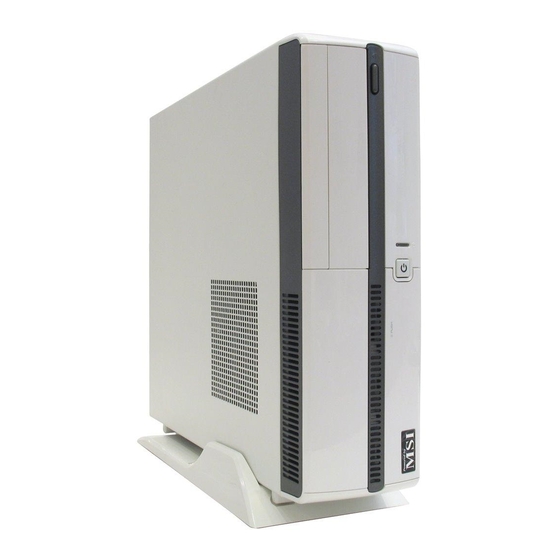
Getting Started Congratulations for purchasing Hetis 915 (MS-6289) barebone. Hetis barebone is your best Slim PC choice. Based on the “all-in-one” design idea, Hetis provides 6 USB ports, 2 full PCI slots for expansion. With the fantastic appearance and small form factor, it can easily be set anywhere. -
Page 9: System Specifications
† Supports up to Celeron-D/Pentium 4 3XX, 56X and 66X Series 533/ 800MHz FSB sequence processor or higher speed. †Supports Intel ® Hyper-Threading Technology (For the latest information about CPU, please visit http://www.msi. com.tw/program/products/slim_pc/slm/pro_slm_cpu_support.php) Chipset † Intel ® 915GL chipset... - Page 10 On-Board Peripherals † Front I/O - Audio Ports (Headphone-Out x 1, Mic-In x 1) - USB2.0 Ports x 2 - IEEE 1394 (4pins) x 1 (For Standard Version) † Rear I/O - PS/2 keyboard/Mouse x 2 - Serial Ports x 2 - VGA Port x 1 - Audio Ports (Line-In x 1, Line-Out x 1, Mic-In x 1, RS-Out x 1, C/S Out x 1, SS-Out x 1)
-
Page 11: System Configuration
Chapter 1 1.2 System Configuration Standard Version Front View 1. Mic-in (pink), Headphone-out (green) 2. 2 x USB 2.0 Ports 3. 4-pin IEEE 1394 Port 4. Power Button & Power LED 5. HDD LED 6. Optical Drive Eject/Close Button 7. Optical Drive (optional) 8. -
Page 12: Rear View
Rear View 1. Voltage Selector 2. Power Jack 3. Ventilation Hole 4. 4 x USB 2.0 Ports 5. PS/2 Mouse 6. PS/2 Keyboard 7. Serial Ports 8. DVI Port 9. S-Video out 10. Mic-in 11. SS-Out Getting Started 12. Power On/Off Switch 13. -
Page 13: Front View
Chapter 1 Lite Version Front View 1. Mic-in (pink), Headphone-out (green) 2. 2 x USB 2.0 Ports 3. Power Button & Power LED 4. HDD LED 5. Optical Drive Eject/Close Button 6. Optical Drive (optional) 7. Card Reader Drive (optional) - Page 14 Rear View 1. Voltage Selector 2. Power Jack 3. Ventilation Hole 4. 4 x USB 2.0 Ports 5. PS/2 Mouse 6. PS/2 Keyboard 7. Serial Ports 8. Mic-in 9. SS-Out Getting Started 10. Power On/Off Switch 11. Support Bracket Spring 12.
-
Page 15: Connecting To External Devices
Chapter 1 Connecting to External Devices... -
Page 16: Chassis Design
Chassis Design † Dimension: 330mm (D) x 320mm (W) x 94mm (H) † Minimized screw structure † Detachable bay housing † Multiple ventilation holes 1. CPU Fan Ventilation Hole 2. System Ventilation Hole 3. System Fan Ventilation Hole Getting Started 4. -
Page 17: Thermal Solution
Chapter 1 1.3 Thermal Solution To prevent the system from overheating, we have adopted a spe- cially designed CPU cooler and multiple ventilation holes for better cool- ing effects. The specially designed CPU cooler supports Intel Prescott™ and Celeron-D™ . The following figures illustrate how the system fan effectively exhausts hot air through multiple ventilation holes. -
Page 18: Getting Started
Sy stem Ventilation Hole Po w e r Po w e r Supply Fan Supply front panel 1-11 Getting Started Ventilation Hole... -
Page 19: System Air Flow Direction
Chapter 1 System Air Flow Direction System Fan Po w e r Supply front panel After the installation is completed, please keep other objects away from the ventila- tion hole at least 2.5cm and above. Do not block the ventilation hole. 1-12 Po w e r Supply... -
Page 20: Chapter 2. Introducing Mainboard
Introducing Mainboard This chapter tells you basics of the CPU, memory modules, and expansion cards, as well as how to setup the jumpers on the mainboard. Also, it provides the instructions on connecting the peripheal devices, such as the mouse, keyboard, etc. While doing the installation, be careful in holding the com- ponents and follow the installation procedures. -
Page 21: Mainboard Layout
Chapter 2 2.1 Mainboard Layout CHRONTEL CH70 21A-TEF JCD1 Re altek ALC880 BIOS CPU_F3 DIMM2 DIMM1 CPU_F 2 CON1 AUDIO2 AUDIO1 USB2 MS-7137 (V1.X) Mainboard (Standard Version) VI A Win bond VT6 307 W836 27TH F CHRONTEL CH7307 TC-DEF Intel ICH6 SATA2 In tel 915GL CASE_OPEN1... - Page 22 Introducing Mainboard Win bond W836 27TH F JCD1 Intel 8254 1P1 Realtek ALC880 Intel ICH6 BIOS CPU_F3 PC IE_1 AT X1 SATA2 SATA1 Inte l 915GL IDE1 JBAT1 DIMM 2 DIMM1 BAT T JPW1 CPU_F2 JFP1 CON1 CASE_OPEN1 AUDIO2 AUDIO1 USB2 USB1 MS-7137 (V1.X) Mainboard (Lite Version)
-
Page 23: Cpu
CPU, make sure to install the cooler to prevent overheating. If you do not have the CPU cooler, contact your dealer to purchase and install them before turning on the computer. MSI Reminds You... Overheating Overheating will seriously damage the CPU and system, always make sure the cooling fan can work properly to protect the CPU from overheating. -
Page 24: Cpu & Cooler Installation
3. Use 2 hands to remove the land side cover (if any). Please note not to touch the pins. MSI Reminds You... 1. Confirm if your CPU cooler is firmly installed before turning on your system. 2. Do not touch the CPU socket pins to avoid damaging. - Page 25 Chapter 2 5. The CPU socket has a plastic cap on it to protect the contact from damage. Before you have installed the CPU, always cover it to protect the socket pin. 7. Lift the load lever up and open the load plate.
- Page 26 Loc k the cooler until its four screws fixed on the mainboard. MSI Reminds You... 1. Check the information in PC Health Status of H/W Monitor in BIOS (Chapter 4) for the CPU temperature. 2. Whenever CPU is not installed, always protect your CPU socket pin with the plastic cap covered to avoid damaging.
-
Page 27: Memory
SDRAM, and supports the memory size up to 2GB without ECC. To oper- ate properly, at least one DIMM module must be installed. (For the updated supporting memory modules, please visit http://www. msi.com.tw/program/products/mainboard/mbd/pro_mbd_trp_list.php ) DDR DIMM Slots (DDR 1~2) Introduction to DDR SDRAM DDR (Double Data Rate) SDRAM is similar to conventional SDRAM, but doubles the rate by transferring data twice per cycle. -
Page 28: Dimm Module Combination
The plastic clip at each side of the DIMM slot will automatically close. MSI Reminds You... You can barely see the golden finger if the module is prop- erly inserted in the socket. Introducing Mainboard... -
Page 29: Power Supply
This 12V power connector is used to provide power to the CPU. ATX1 JPW1 MSI Reminds You... These two connectors connect to the power supply and have to work together to ensure stable operation of the mainboard. ATX1 Pin Definition SIGNAL 3.3V... -
Page 30: Front Panel
2.5 Front Panel Headphone-out Mic-in Audio Ports These audio ports allow you to connect front audio devices. Headphone-out USB Ports The mainboard provides a UHCI (Universal Host Controller Interface) Universal Serial Bus root for attaching USB devices such as keyboard, mouse or other USB-compatible devices. You can plug the USB devices directly into these connectors. -
Page 31: Rear Panel
Chapter 2 2.6 Rear Panel The Rear Panel provides the following connectors: IEEE 1394 6pins (For Standard Version) LAN Jack Mouse Keyboard USB Ports Mouse/Keyboard Connectors The mainboard provides two standard PS/2 ® for attaching PS/2 mouse and keyboard. PS/2 Mouse (6-pin Female) PS/2 Keyboard (6-pin Female) Serial Port VGA Port... -
Page 32: Audio Port Connectors
Audio Port Connectors The left 3 audio jacks are for 2-channel mode for stereo speaker output: Line Out is a connector for Speakers or Headphones. Line In is used for external CD player, Tape player, or other audio devices. Mic is a connector for microphones. -
Page 33: Digital Panel Connector (Dvi)(Standard Only)
Chapter 2 Digital Panel Connector (DVI)(Standard only) The mainboard provides a DVI (Digital Visual Interface) connector which allows you to connect an LCD monitor. The DVI connector provides a high-speed digital interconnection between the computer and its display device. To connect a LCD monitor, simply plug your monitor cable into the DVI connector on the mainboard, and make sure that the other end of the cable is properly connected to your monitor. -
Page 34: Lan (Rj-45) Jack
LAN (RJ-45) Jack The mainboard provides 1 standard RJ-45 jack for connection to single Local Area Network (LAN). This Giga-bit LAN enables data to be transferred at 1000, 100 or 10Mbps. You can connect a network cable to it. RJ-45 LAN Jack USB Ports The mainboard provides a UHCI (Universal Host Controller Interface) Universal Serial Bus root for attaching USB devices such as... -
Page 35: Serial Ports
Chapter 2 Serial Ports The mainboard offers two 9-pin male DIN connectors as serial ports. The ports are 16550A high speed communication ports that send/receive 16 bytes FIFOs. You can attach a serial mouse or other serial devices directly to the connectors. 1 2 3 4 5 6 7 8 9 9-Pin Male DIN Connector... -
Page 36: S-Video Out Connector (Standard Only)
Introducing Mainboard S-Video Out Connector (For Standard Version) The mainboard provides a S-Video Out connector for video-out function which allows you to output the image to a TV or video device. Simply plug one end of the S-Video cable into the S-Video Out connector on the mainboard, and the other end to the video input connector on your TV or video device. -
Page 37: Connectors
Chapter 2 2.7 Connectors IDE Connector: IDE1 The mainboard has a 32-bit Enhanced PCI IDE and Ultra DMA 33/ 66/100 controller that provides PIO mode 0~4, Bus Master, and Ultra DMA/33/66/100 function. The connectors on the mainboard allows you to connect to the IDE devices: HDD & CD-ROM. Card Reader Connector: CR1 The mainboard provides a connector to connect the Card Reader on the Front Panel. -
Page 38: Serial Ata Connectors: Sata1/Sata2
ADT7467 chipset to detect CPU/fab temperature, you must use a spe- cially designed fan with speed sensor to take advantage of the CPU fan control. MSI Reminds You... 1. Always consult the vendors for proper CPU cooling fan. 2. Please refer to the recommended CPU fans at Intel website. -
Page 39: Front Panel Connectors: Jfp1
Chapter 2 Front Panel Connectors: JFP1 The mainboard provides one front panel connector for you to connect to the front panel switches and LEDs. JFP1 is compliant with ® Intel Front Panel I/O Connectivity Design Guide. SIGNAL HD_LED_P FP PWR/SLP HD_LED_N FP PWR/SLP RST_SW_N... -
Page 40: Internal Speaker Connector: Con1
RCA out Connector: J2 (For Standard Version) The mainboard provides a TV-out connector for you to connect to a TV or video device. Internal Speaker Connector: CON1 This connector is used to connect the built-in speaker. Introducing Mainboard CON1 2-21... -
Page 41: Jumper
Jumper ) to clear data. Follow the instructions below to clear the data: JBAT1 MSI Reminds You... You can clear CMOS by shorting 2-3 pin while the system is off. Then return to 1-2 pin position. Avoid clearing the CMOS while the system is on;... -
Page 42: Slot
2.9 Slot PCI Express Slot: PCIE_1 (For Riser Card Use Only) The mainboard provides one PCI Express slot. The PCI-E slot allows you to insert Riser Cards. The Riser Cards are included in the barebone. The Riser Cards allows you to insert two expansion card. -
Page 43: Chapter 3. System Assembly
System Assembly System Assembly This chapter provides you with the installation procedures of Midas barebone. It is useful for you to read the information of mainboard setup before assembling the whole system. -
Page 44: Overview
Chapter 3 3.1 Overview The built-in MS-7137 mainboard is designed for Hetis barebone only. Except MS-7137 mainboard, the built-in components of the barebone include power supply. In this chapter we’ll show you how to install CPU, Card Reader, HDD, Optical Drives and CPU Cooler. Installation Tools Screw Driver Screws... -
Page 45: Checking The Items
System Assembly Checking the Items Before assembling your system, please check the items listed below for basic system operation. The Footstand and the CPU cooler are included in the package, other items are optional. Footstand CPU Cooler Optical Drive (Optional) CPU (Optional) IDE or SATA HDD (Optional) DDR SDRAM (Optional) -
Page 46: Installation Procedures
Chapter 3 3.2 Installation Procedures 1. Removing Cover Unlock the two screws on the backplane with hands. Remove the chassis cover. Press the level on the support bracket spring to release it. Unlock the screw on the front panel to release the drive cage. -
Page 47: Installing Hdd
System Assembly 2. Installing HDD Lift the drive cage to slide aside. Pull the HDD tray forwards to remove it from the chassis. Put the HDD in the HDD tray and use 4 screws to fix it on both sides. Connect the cable and the power cord to the HDD, then put the HDD tray back... -
Page 48: Installing Optical Drive
Chapter 3 3. Installing Optical Drive Pull the lock brackets outwards on the both sides to release. Insert the optical drive and push the lock brackets back to fix it. Connect the cable and the power cord to the optical drive, then restore the drive cage. -
Page 49: Installing Card Reader (Optional)
System Assembly 4. Installing Card Reader (Optional) Use the screwdriver to unlock the card reader cage. Insert the card reader into the cage with 15 degree angle. Insert the LED into the cage and lock the card reader with two screws. Restore the card reader back and connect the cable to the CR1 connec- tor on the mainboard. -
Page 50: Installing Memory Modules
Chapter 3 5. Installing Memory Modules Locate the DIMM slots. Insert the DIMM vertically into the slot. Note: The DIMM has only one notch on the center of module. It will only fit in the right direction. -
Page 51: Installing Cpu
System Assembly 6. Installing CPU Locate the CPU socket. Pull the lever away from the socket and raise it up, then lift up the cover. Put the CPU onto the socket. Note: Make sure the pins are completely embedded into the socket. The CPU can only fit in the correct direction. -
Page 52: Installing Cpu Cooler
Chapter 3 7. Installing CPU Cooler Place the CPU cooler onto the CPU socket and secure the four screws. Connect the CPU cooler’s power cord to the connector on the mainboard. 3-10... -
Page 53: Restoring Chassis Cover & Installing Footstand
System Assembly 8. Restoring Chassis Cover & Installing Footstand Restore the support bracket. Restore the chassis cover. Lock the chassis cover with the screws. Put the PC on the footstand or lay Tower type on the rubber foots. Horizontal type 3-11... -
Page 54: Chapter 4. Bios Setup
² You want to change the default settings for customized features. MSI Reminds You... 1. The items under each BIOS category described in this chap- te r a re u nde r c ont inu ous upd ate fo r b ette r s y s t em performance. -
Page 55: Entering Setup
Chapter 4 Power on the computer and the system will start POST (Power On Self Test) process. W hen the message below appears on the screen, press <DEL> key to enter Setup. DEL: Setup Menu TAB: Logo If the message disappears before you respond and you still wish to enter Setup, restart the system by turning it OFF and On or pressing the RESET button. -
Page 56: Control Keys
The preset Optimal Defaults of the BIOS setup program provide optimal perfor- mance settings for all devices and the system. MSI Reminds You... The items under each BIOS category described in this chapter are under continuous update for better system performance. -
Page 57: The Main Menu
Chapter 4 The Main Menu Once you enter AMIBIOS NEW SETUP UTILITY, the Main Menu will appear on the screen. Use arrow keys to move among the items and press <Enter> to enter the sub-menu. Standard CMOS Features Use this menu for basic system configurations, such as time, date etc. Advanced BIOS Features ®... - Page 58 BIOS Setup Load Optimized Defaults Use this menu to load the default values set by the mainboard manufacturer specifically for optimal performance of the mainboard. BIOS Setting Password Use this menu to set the password for BIOS. Save & Exit Setup Save changes to CMOS and exit setup.
-
Page 59: Standard Cmos Features
Chapter 4 Standard CMOS Features The items in Standard CMOS Features Menu includes some basic setup items. Use the arrow keys to highlight the item and then use the <+> or <-> keys to select the value you want in each item. Date (MM:DD:YY) This allows you to set the system to the date that you want (usually the current date). - Page 60 Device/Vendor/Size This item shows the information about the specified item. Read-only. LBA/Large M ode This item allows you to enable or disable the LBA (Logical Block Address, the logical block size in hard disk) mode. Setting options: [Auto], [Disabled]. Hard Disk S.M.A.R.T. This allows you to activate the S.M.A.R.T.
-
Page 61: Advanced Bios Features
Chapter 4 Advanced BIOS Features Quick Boot Setting the item to [Enabled] allows the system to boot within 5 seconds since it will skip some check items. Available options: [Enabled], [Disabled]. Boot Sector Protection This function protects the BIOS from accidental corruption by unauthorized users or computer viruses. - Page 62 In this way, the system performance is highly improved. If you disable the function, the processor will use only one core to execute the instructions. Settings: [Enabled], [Disabled]. MSI Reminds You... Enabling the functionality of Hyper-Threading Technology for your computer system requires ALL of the following platform Components:...
-
Page 63: Advanced Chipset Features
Chapter 4 Advanced Chipset Features MSI Reminds You... Change these settings only if you are familiar with the chipset. Configure DRAM Timing by SPD Selects whether DRAM timing is controlled by the SPD (Serial Presence Detect) EEPROM on the DRAM module. Setting options: [Disabled], [Enabled]. -
Page 64: Integrated Peripherals
BIOS Setup Integrated Peripherals USB Controller This setting is used to enable/disable the onboard USB host controller. Setting options: [Disabled], [Enabled]. USB Device Legacy Support Set to [Enabled] if you need to use any USB 1.1/2.0 device in the operating system that does not support or have any USB 1.1/2.0 driver installed, such as DOS. - Page 65 Chapter 4 PCI IDE BusM aster Set this option to [Enabled] to specify that the IDE controller on the PCI local bus has bus mastering capability. Settings options: [Disabled], [Enabled]. I/O Devices Configuration Press <Enter> to enter the sub-menu and the following screen appears: COM Port 1/2 These items specify the base I/O port addresses of the onboard Serial Port 1 (COM A) / Serial Port 2 (COM B).
- Page 66 AHCI For the setting options of Configure SATA as, select [IDE] if you want to have SATA as IDE function. Select [AHCI] to allow the SATA to have Ad- vanced Host Controller Interface (AHCI) feature, which supports improved serial ATA disk performance with native command queuing & native hot plug.
-
Page 67: Power Management Features
Chapter 4 Power Management Features MSI Reminds You... S3-related functions described in this section are available only when your BIOS supports S3 sleep mode. ACPI Standby State This item specifies the power saving modes for ACPI function. If your operat-... - Page 68 Power Button Function This feature allows users to configure the Power Button function. Settings are: [Power Off] [Suspend] Restore on AC Power Loss This setting specifies whether your system will reboot after a power failure or interrupt occurs. Available settings are: [Off] Leaves the computer in the power off state.
- Page 69 Chapter 4 Resume by Ring An input signal on the serial Ring Indicator (RI) line (in other words, an incoming call on the modem) awakens the system from a soft off state. Resume by PCI/PCI-E Device This controls how and whether the system can be powered on by the devices installed on PCI/PCI-E slots.
-
Page 70: Pnp/Pci Configurations
PNP/PCI Configurations This section describes configuring the PCI bus system and PnP (Plug & Play) feature. PCI, or Peripheral Component Interconnect, is a system which allows I/O devices to operate at speeds nearing the speed the CPU itself uses when communicating with its special components. -
Page 71: H/W Monitor
Chapter 4 This section shows the status of your CPU, fan, overall system status, etc. Monitor function is available only if there is hardware monitoring mechanism Chassis Intrusion The field enables or disables the feature of recording the chassis intrusion status and issuing a warning message if the chassis is once opened. -
Page 72: Bios Setting Password
BIOS Setup BIOS Setting Password W hen you select this function, a message as below will appear on the screen: Type the password, up to six characters in length, and press <Enter>. The password typed now will replace any previously set password from CMOS memory. -
Page 73: Load Fail-Safe/Optimized Defaults
Chapter 4 Load Fail-Safe/Optimized Defaults The two options on the main menu allow users to restore all of the BIOS settings to the default Fail-Safe or Optimized values. The Optimized Defaults are the default values set by the mainboard manufacturer specifically for optimal performance of the mainboard. -
Page 74: Chapter 5. Introduction To Realtek Alc880
Introduction to Realtek ALC 880 Introduction to Realtek ALC880 The mainboard is equipped with Realtek ALC880 chip, which provides support for 8-channel audio output, including 2 Front, 2 Rear, 2 Side, 1 Center and 1 Subwoofer channel. ALC880 allows the board to attach 2, 4, 6 or 8 speakers for better surround sound effect. -
Page 75: Installing The Realtek Hd Audio Driver
1. Insert the companion CD into the CD-ROM drive. The setup screen will auto- matically appear. 2. Click Realtek HD Audio Driver. MSI Reminds You... The HD Audio Configuration update to enhance audio applications. Hence, the program screens shown here in this appendix may be slightly different from the latest software utility and shall be held for reference only. - Page 76 3. Click Next to install the Realtek High Definition Audio Driver. 4. Click Finish to restart the system. Introduction to Realtek ALC 880 Clic k he r e Clic k he r e Se le ct this option...
-
Page 77: Software Configuration
Chapter 5 Software Configuration After installing the audio driver, you are able to use the 2-, 4-, 6- or 8- channel audio feature now. Click the audio icon from the system tray at the lower-right corner of the screen to activate the HD Audio Configuration. It is also available to enable the audio driver by clicking the Azalia HD Sound Effect Manager from the Control Panel. -
Page 78: Sound Effect
Sound Effect Here you can select a sound effect you like from the Environment list. You may choose the provided sound effects, and the equalizer will adjust automatically. If you like, you may also load an equalizer setting or make an new equalizer setting to save as an new one by using the “Load EQ Setting”... -
Page 79: Audio Io
Chapter 5 Audio IO In this tab, you can easily configure your multi-channel audio function and speakers. You can choose a desired multi-channel operation here. a. Headphone for the common headphone b. 2CH Speaker for Stereo-Speaker Output c. 4CH Speaker for 4-Speaker Output d. - Page 80 Introduction to Realtek ALC 880 Correct M essage Assume to plug a headphone in the Green jack at back panel. The icon beside green jack become visible and the dialogue “connected device” pops up. Check the headphone, then click OK. As soon as OK is clicked, the icon beside green jack becomes “headphone”...
- Page 81 Chapter 5 Test Speakers You can select the speaker by clicking it to test its functionality. The one you select will light up and make testing sound. If any speaker fails to make sound, then check whether the cable is inserted firmly to the connector or replace the bad speakers with good ones.
-
Page 82: Mixer
Realtek HD Audio rear output or Realtek HD Audio front output items. MSI Reminds You... Before set up, please make sure the playback devices are well plugged in the jacks on the rear or front panel. The Realtek HD Audio front output item will appear after you pluging the speakers into the jacks on the front panel. - Page 83 Chapter 5 W hen you are playing the first audio source (for example: use W indows Media Player to play DVD/VCD), the output will be played from the rear panel, which is the default setting. Then you must to select the Realtek HD Audio front output from the scroll list first, and use a different program to play the second audio source (for example: use W inamp to play MP3 files).
- Page 84 Mic in at front panel (Pink) from the scroll list after connecting microphone to the front audio panel. MSI Reminds You... Only the speakers that plugged into the Line-Out jack (the green ne) on the back panel will be functional when you intend to listen to the audio that has been recorded from the microphone.
-
Page 85: Microphone
Chapter 5 Microphone In this tab you may set the function of the microphone. Select the Noise Suppression to remove the possible noise during recording, or select Acoustic Echo Cancelltion to cancel the acoustic echo druing recording. Also, please use the drop-down list to choose the recording source from Realtek HD Audio real input or Realtek HD Audio front input. -
Page 86: Audio Demo
Introduction to Realtek ALC 880 3D Audio Demo In this tab you may adjust your 3D positional audio before playing 3D audio applications like gaming. You may also select different environment to choose the most suitable environment you like. 5-13... -
Page 87: Information
Chapter 5 Information In this tab it provides some information about this HD Audio Configuration utility, including Audio Driver Version, DirectX Version, Audio Controller & Audio Codec. You may also select the language of this utility by choosing from the Language list. Also there is a selection Show icon in system tray. -
Page 88: Using 2-, 4-, 6- & 8- Channel Audio Function
Using 2-, 4-, 6- & 8- Channel Audio Function Connecting the Speakers W hen you have set the Multi-Channel Audio Function mode properly in the software utility, connect your speakers to the correct phone jacks in accordance with the setting in software utility. n 2-Channel M ode for Stereo-Speaker Output Refer to the following diagram and caption for the function of each phone jack on the back panel when 2-Channel Mode is selected. - Page 89 Chapter 5 n 4-Channel M ode for 4-Speaker Output 4-Channel Analog Audio Output Line In Line Out (Front channels) Line Out (Rear channels) Line Out (Center and Subwoofer channel, but no functioning in this mode) Side Surround Out (Side channels, but no functioning in this mode) Description: Connect two speakers to back panel’s Line Out connector and...
- Page 90 n 6-Channel M ode for 6-Speaker Output 6-Channel Analog Audio Output Line In Line Out (Front channels) Line Out (Rear channels) Line Out (Center and Subwoofer channel) Side Surround Out (Side channels, but no functioning in this mode) Introduction to Realtek ALC 880 Description: Connect two speakers to back panel’s Line Out connector, two...
- Page 91 Chapter 5 n 8-Channel M ode for 8-Speaker Output 8-Channel Analog Audio Output Line Out (Side channels) Line Out (Front channels) Line Out (Rear channels) Line Out (Center and Subwoofer channel) Side Surround Out (Side channels) Description: Connect two speakers to back panel’s Line Out connector, two speakers to the rear-channel, two speakers to the c enter/...
Need help?
Do you have a question about the Hetis 915 and is the answer not in the manual?
Questions and answers